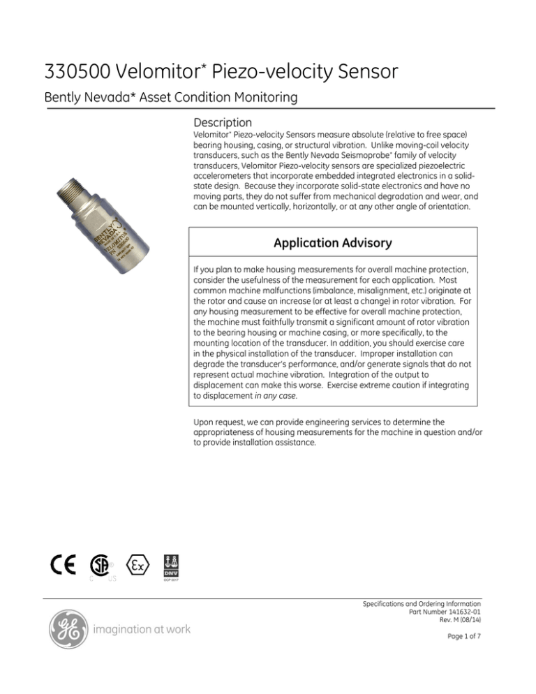
330500 Velomitor* Piezo-velocity Sensor
Bently Nevada* Asset Condition Monitoring
Description
Velomitor* Piezo-velocity Sensors measure absolute (relative to free space)
bearing housing, casing, or structural vibration. Unlike moving-coil velocity
transducers, such as the Bently Nevada Seismoprobe* family of velocity
transducers, Velomitor Piezo-velocity sensors are specialized piezoelectric
accelerometers that incorporate embedded integrated electronics in a solidstate design. Because they incorporate solid-state electronics and have no
moving parts, they do not suffer from mechanical degradation and wear, and
can be mounted vertically, horizontally, or at any other angle of orientation.
Application Advisory
If you plan to make housing measurements for overall machine protection,
consider the usefulness of the measurement for each application. Most
common machine malfunctions (imbalance, misalignment, etc.) originate at
the rotor and cause an increase (or at least a change) in rotor vibration. For
any housing measurement to be effective for overall machine protection,
the machine must faithfully transmit a significant amount of rotor vibration
to the bearing housing or machine casing, or more specifically, to the
mounting location of the transducer. In addition, you should exercise care
in the physical installation of the transducer. Improper installation can
degrade the transducer’s performance, and/or generate signals that do not
represent actual machine vibration. Integration of the output to
displacement can make this worse. Exercise extreme caution if integrating
to displacement in any case.
Upon request, we can provide engineering services to determine the
appropriateness of housing measurements for the machine in question and/or
to provide installation assistance.
Specifications and Ordering Information
Part Number 141632-01
Rev. M (08/14)
Page 1 of 7
Specifications
Maximum Cable
Length
Parameters are specified from +20 °C to +30 °C (+68
°F to +86 °F) and at 100 Hz unless otherwise
indicated.
Note:
Operation outside the specified limits may result in false
readings or loss of machine monitoring.
Electrical
Sensitivity
3.94mV/mm/s (100 mV/in/s) ±5%.
305 metres (1,000 feet) of cable,
part number 02173006, with no
degradation of signal.
Hazardous Area Approvals
Multiple approvals for hazardous areas certified by
Canadian Standards Association (CSA) in North
America and by LCIE in Europe.
North America
Ex ia IIC T4
Frequency
Response
AEx ia IIC T4
Class I, Div 1, Groups A, B, C, D
4.5 Hz to 5 kHz (270 cpm to 300
kcpm) ±3.0 dB.
Class II, Groups E, F, G
6.0 Hz to 2.5 kHz (360 cpm to 150
kcpm) ±0.9 dB.
when installed per dwg 167537
Class III
T4 @ -40°C ≤ Ta ≤ 100°C
Ex nL IIC T4
Temperature
Sensitivity
AEx nA IIC T4
Class I, Div 2, Groups A, B, C, D
when installed per dwg 167537
-14% to +7.5% typical over the
operating temperature range.
Velocity Range
T4 @ -40°C ≤ Ta ≤ 100°C
European/ATEX
1270 mm/s (50 in/s) peak.
II 1 G
Ex ia IIC T4 Ga
Transverse
Sensitivity
T4 @ -55°C ≤ Ta ≤ 121°C
Less than 5% of sensitivity.
II 3 G
Amplitude
Linearity
Ex nA IIC T4 Gc
T4 @ -55°C ≤ Ta ≤ 121°C
±2% to 152 mm/s (6 in/s) peak.
IECEx
Mounted
Resonant
Frequency
Ex ia IIC T4 Ga
Ex nA IIC T4 Gc
T4 @ -55°C ≤ Ta ≤ 121°C
Greater than 12 kHz.
Brazil
Broadband
Noise Floor (4.5
Hz to 5 kHz)
Ex ia IIC T4 Ga
T4 @ -40°C ≤ Ta ≤ 100°C
0.004 mm/s (160 μin/s) rms,
nominal
Specifications and Ordering Information
Part Number 141632-01
Rev. M (08/14)
Page 2 of 7
Environmental Limits
Polarity
Pin A goes positive with respect to
pin B when the sensor case
motion is toward the connector.
Operating
Temperature
Range
55 °C to 121 °C (67 °F to
250 °F).
Ordering Information
Velomitor Piezo-velocity Sensor
330500-AXX-BXX
Shock
Survivability
5000 g peak, maximum
A:
Relative
Humidity
To 100% non-submerged; case is
hermetically-sealed.
Base Strain
Sensitivity
0.005 in/s/µstrain.
Magnetic Field
Susceptibility
<51 µin/s/gauss (50 gauss, 5060Hz).
B:
Mounting Thread Adapter Option
00
No adapter
01
1/2 - 20 UNF
02
M8 x 1
03
1/4 - 28 UNF
04
1/4 - 20 UNC
05
Unavailable for 330500.
For 1/4-18 NPT mounting,
order 330525.
06
5/8 – 18 UNF
07
3/8 – 16 UNC
08
1/2 – 13 UNC
Agency Approval Option
00
Not required
01
CSA/US/C
02
ATEX (European)
04
Multiple approvals (CSA, ATEX)
Note: Country specific approvals may be available. Contact
your local customer care representative.
Physical
Weight
142 grams (5.0 oz), typical.
Diameter
25.3 mm (0.995 in).
Height
63.2 mm (2.49 in).
Case Material
316L stainless steel.
Connector
2-pin Mil-C-5015 hermeticallysealed, 316L stainless steel shell.
Mounting
Torque
46 kg cm (40 in-lb) max.
Specifications and Ordering Information
Part Number 141632-01
Rev. M (08/14)
Page 3 of 7
84661
Interconnect Cables
AXX
A:
2-conductor twisted, shielded 22
AWG armored cable with 2socket moisture-resistant female
connector at one end, terminal
lugs at the other end.
Cable length Option in feet
For the cables listed below, order
in increments of 1.0 ft (305 mm).
Example: 0 9 = 9 ft
Used with monitors. Not for use
with 21128 Velocity Transducer
Housing.
1 2 = 12 ft
Minimum length: 3.0 ft (0.9 m)
The following are standard lengths
Feet
Metres (approx.)
6
1.8
8
2.4
10
3.0
12
3.6
15
4.5
17
5.0
20
6.0
25
7.6
30
9.0
33
10.0
50
15.2
99
30.0
NOTE: Non-standard/custom lengths
can also be ordered at additional cost
Maximum length: 96 ft (29 m).
89477
2-conductor 18 AWG twisted,
shielded cable with right angle 2socket plug at one end, terminal
lugs at the other end.
Used with monitors and with
21128 Velocity Transducer
Housing.
Minimum length: 2.0 ft (0.6 m)
Maximum length: 99 ft (30 m).
125065
2-conductor 18 AWG twisted,
shielded cable with 2-socket plug
and fluorosilicone elastomer boot
at one end, terminal lugs at the
other.
9571
2-conductor twisted, shielded 22
AWG cable with 2-socket
moisture-resistant female
connector at one end, terminal
lugs at the other end.
Used with monitors. Not for use
with 21128 Velocity Transducer
Housing.
Used with monitors. Not for use
with 21128 Velocity Transducer
Housing.
Minimum length: 2.0 ft (0.6 m)
Maximum length: 99 ft (30 m).
Minimum length: 2.0 ft (0.6 m)
Maximum length: 99 ft (30 m)
Specifications and Ordering Information
Part Number 141632-01
Rev. M (08/14)
Page 4 of 7
Velocity Transducer Housing Assembly
21128-AXX-BXX
A:
Mounting Thread Option
01
Unthreaded
02
3/4 - 14 NPT
03
1/2 - 14 NPT
04
1/2 - 12 BSP
B:
Cable Exit Fitting Option
01
1/2 - 14 NPT plug
02
1/2 -14 NPT explosion-proof
03
1/2 -14 NPT explosion-proof
with cable gland seal
Note:
When using the 21128 housing,
cable part number 89477-AA is
necessary to connect the
Velomitor Sensor to a monitor.
Used with 1/4 - 28 UNF mounting
thread adapters.
46122-01
Quick Connect for
semi-permanent mounting of
Velomitor Sensors. Used with
1/2 - 20 UNF mounting thread
adapters.
89409-01
Individual 1/2 - 20 UNF
mounting adapter.
89410-01
Individual M8 x 1 mounting
adapter.
89411-01
Individual 1/4 - 28 UNF
mounting adapter.
Velocity Transducer Housing – CENELEC approved
107770-AXX-BXX
This version is a combination of the 330500
Velomitor Sensor and a 21128 Housing pre-installed
at the factory. It is also rated for CENELEC Zone 1,
Group IIC hazardous area applications.
A:
B:
Mounting Thread Option
01
Unthreaded
02
3/4 - 14 NPT
03
1/2 - 14 NPT
04
1/2 - 14 BSP
Cable Exit Fitting Option
01
1/2 - 14 NPT plug
02
1/2 - 14 NPT explosion-proof
03
1/2 - 14 NPT explosion-proof
with cable gland seal
Accessories
89412-01
Individual 1/4 - 20 UNC
mounting adapter.
89413-01
Individual 1/4 - 18 NPT mounting
adapter. Spares only. For new
installations, order 330525
velometer.
04300015
Individual 5/8 - 18 UNF
mounting adapter.
161191
Individual 1/2 - 13 UNC
mounting adapter.
100076-01
330500 Velomitor Sensor and
Velomitor XA Sensor Manual.
Note:
02173006
Bulk cable; 2 conductor 18 AWG
twisted, shielded cable without
connectors or terminal lugs.
Specify number of feet.
The Velomitor Sensor is shipped
with an adapter. Individual
adapters are available as spares.
101212-01
Velomitor Sensor connector kit.
Used with housings and retrofits.
123135-01
46000-01
Magnetic Base for temporary
mounting of Velomitor Sensors.
Velomitor Sensor Power Module.
Specifications and Ordering Information
Part Number 141632-01
Rev. M (08/14)
Page 5 of 7
Graphs and Figures
1
2
63.2
(2.49)
3
4
5
1.
2-pin, MIL-C-5015 receptacle
2.
15/16 inch hexagonal
3.
12.7 (0.500) diameter, 0.8 (0.030) deep counterbore
4.
25.3 (0.995) diameter
5.
3/8-24 UNF-2B, 6.4 (0.250) minimum threaded depth, 14.0 (0.550) maximum drill depth
Figure 1: Velomitor Piezo-Velocity Sensor Dimensional Drawing
Specifications and Ordering Information
Part Number 141632-01
Rev. M (08/14)
Page 6 of 7
dB referenced to 100 Hz
2
1
0
-1
-2
1
10
100
1000
10000
Frequency (Hz)
Figure 2: Typical Amplitude Response
100
Phase Lag Angle (degrees)
80
60
40
20
0
-20
1
10
100
1000
10000
Frequency (Hz)
Figure 3: Typical Phase Response
* Denotes trademarks of Bently Nevada, Inc., a wholly owned subsidiary of General Electric Company.
© 1999 – 2014 Bently Nevada Inc. All rights reserved.
Printed in USA. Uncontrolled when transmitted electronically.
1631 Bently Parkway South, Minden, Nevada USA 89423
Phone: 775.782.3611
Fax: 775.215.2873
www.ge-mcs.com/bently
Specifications and Ordering Information
Part Number 141632-01
Rev. M (08/14)
Page 7 of 7


