ULTRA^^ PRESSURE CONTROL A
advertisement

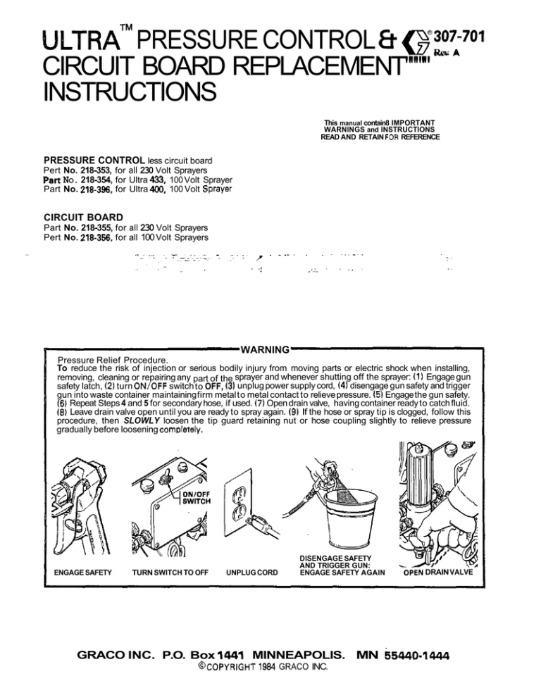
ULTRA^^ PRESSURE CONTROL a ~ 3 0 7 - 7 0 1 CIRCUIT BOARD REPLACEMENT"""'" INSTRUCTIONS Rev A This manual contain8 IMPORTANT WARNINGS and INSTRUCTIONS READ AND RETAIN FOR REFERENCE PRESSURE CONTROL less circuit board Pert No. 218-353, for all 230 Volt Sprayers pert NO. 218-354, for Ultra 433, 100 Volt Sprayer Part No. 218-396, for Ultra 100 Volt Sprayer 400. CIRCUIT BOARD Part No. 218-355, for all 230 Volt Sprayers Pert No. 218-356, for all 100 Volt Sprayers WARNING Pressure Relief Procedure. To reduce the risk of injection or serious bodily injury from moving parts or electric shock when installing, removing, cleaning or repairing any part of the sprayer and whenever shutting off the sprayer: (1) Engage gun safety latch, 12) turn ON/OFF switch to OFF, (3) unplug power supply cord, (4) disengage gun safety and trigger gun into waste container maintaining firm metal to metal contact to relieve pressure. 15) Engage the gun safety. 16) Repeat Steps 4 and 5 for secondary hose, if used. (7) Open drain valve, having container ready to catch fluid. (8) Leave drain valve open until you are ready to spray again. (9) If the hose or spray tip is clogged, follow this procedure, then SLOWLY loosen the tip guard retaining nut or hose coupling slightly to relieve pressure gradually before loosening comDletely. ENGAGE SAFETY TURN SWITCH TO OFF UNPLUG CORD DISENGAGE SAFETY AND TRIGGER GUN: ENGAGE SAFETY AGAIN GRACO INC. P.O. Box 1441 MINNEAPOLIS. MN @COPYRIGHT 1984 GRACO INC. OPEN DRAIN VALVE 65440-1444 CIRCUIT BOARD REPLACEMENT Tools Needed: To remove the board from the box, pull out the black plastic-tipped pin (330). Push the boftom of the circuit board toward the wall of the box and carefully slide the board out. 5. Install the board in the box at the same angle as it was removed. 6. Reconnect ell wires. Refer to the wiring diagram on page 3. 4. Phillips screwdriver Needle nose pliers WARNING Relief Procedure Warning on the front cover to reduce the risk of an injection injury, injury from moving parts, or electric shock. Be sure to unplug CAUTION 1. Remove the pressure control cover and screws. 2. Turn the pressure control knob all the way counterclockwise to the minimum setting to release spring tension on the board. Also check.to be sure only three or four threads of the pressure control knob shaft are exposed below the pressure adjustment nut (SI.Backdown the nut, if necessary. See Fig 1. CAUTION Be sure the flat blade of the insulated male connectors are centered exactly in the wraparound blade of the female connector when connections are made. Route all wires carefully to avoid interference with the circuit board, bourdon tube and pressure control cover. Step 2 is essential to reduce the risk of damaging the circuit board while removing or installing it. These precautions are essential to reduce the risk of malfunction. 3. DisconnectALL wires from the board, including the two heavy black wires. Pay close attention to where 7. Perform the Stall Pressure Calibration on page 5 i you installed a new board. connections are made. Fig 1 ' ' WIRING DIAGRAM ALL PRESSURE CONTROLS AND CIRCUIT BOARDS rONlOFFSWlTCH THESE WIRES ARE CONNECTED TO TWO TERMINALS ON THE OTHER SIDE OF THE ONlOFF SWITCH CIRCUIT BOARD .' MICROSWITCH 'P18 MOTOR YELLOWlQREEN QROUNO WIRE 307-701 3 PRESSURE CONTROL REPLACEMENT (Refer to Fig 3) Tools Needed: Phillips screwdriver 13 mm ( 1 / 2 ) open end wrench 19 mm 13/4") open end wrench Adjustable wrench Small screwdriver WARNING Relief. Procedure Warning on the front cover to reduce the risk of an injection injury, injury from moving parts, or electric shock. Be sure to unplug 1. Disconnect the main fluid hose (23) and the secondary fluid hose, if used, from the sprayer. 2. Disconnect the fluid hose (47) from between the displacement pump outlet nipple (46)and pressure control inlet elbow (88). 3. Loosen the filter bracket nut (85)and washer (13) a 19 mm open end wrench. ... . using . Holdthe'pressure control adapter 186) firmly with a 19 mm oDen end wrench. Use an adiustable wrench to loosen the swivel union (79), then remove the fluid filter (48). 5. Remove the pressure control cover and screws (36,871, and disconnect the four motor leads at the appropriate terminals. 6. Refer to "Circuit Board Replacement" on page 2, remove the circ,uit board and retain. 7. Remove the conduit (22). 8. Use a 13 mm open end wrench to loosen and remove the pressure control mounting screws (44) and washers 140) located below the Dressure control box. Remove the box. 9. Install the new pressure control assembly in the reverse order of disassembly. 4 : - ~~~ ~ ~ 10. Perform the Stall Pressure Adjustment Procedure on page 5, before regular operation of the sprayer. 4 307-701 Fig 3 PRESSURE CONTROL CALIBRATION USE EXTREME CAUTION WHEN PERFORMING THIS CALIBRATION PROCEDURE to reduce the risk of an injection injury or other serious bodily injury which can result from component rupture, electric shock, fire, explosion, or moving parts. , This procedure sets the Ultra 433 sprayer to 210' bar (3000 psi) MAXIMUM WORKING PRESSURE and the Ultra 400 sprayer to 192 bar (2750 psi) MAXIMUM WORKING PRESSURE. This procedure must be performed whenever a new or used circuit board or pressure control assembly is removed and reinstalled or replaced to be sure the sprayer is properly calibrated. . . NEVER ammpt to increase the fluid outlet pressure by performing this calibration in any other way. NEVER EXCEED the stated MAXIMUM WORKING PRESSURE OF YOUR SPRAYER. Normal operation of the sprayer at higher pressures could result in component rupture, fire or explosion. AVOID touching the wires in the pressure control assembly when the control box cover is removed to reduce the risk of electric shock. Improper calibration can cause the sprayer to overpressurize and result in component rupture, fire or explosion. It may also prevent the sprayer from obtaining the maximum working pressure which would result in poor sprayer performance. Tools Needed: Phillips screwdriver 9 mm ignition wrench Stell Pressure Adjustment (See Fig 4) NOTE: Perform this procedure only after completing "Overpressurization Shutoff Adjustment" unless otherwise instructed in another procedure. 1. Turn the sprayer switch to OFF. Turn the pressure control knob counterclockwise to the minimum setting. Disengage the gun safety latch and trigger the gun into a waste container until pressure is relieved. Engage the gun safety latch. 2. Use a 9 mm ignition wrench to turn the pressure adjustment nut IS) counterclockwise about two full turns. 3. With the pressure control knob at the minimum setting, turn the sprayer switch ON. CAUTION Topreventpump corrosion, flush the water out of the pump, hose and gun with mineral spirits. Be sure to close the drain valve, first. Use the lowest pressure necessary to flush. Relieve the pressure as stated in the WARNING, above. Leave the mineral spirits in the pump to protect it until you are aready to spray again. ON/OFFSWITCH7 THE SPRAYER SHOULD NOT STARTI If it does start, shut the sprayer switch OFF, disengage the gun safety latch, trigger the gun into a waste container until pressure is relieved. Engage the gun safety latch. Turn the pressure adjustment nut ( S )a little further counterclockwise. Turn the sprayer on to be sure it does not start. 4. Slowly turn the pressure control knob clockwise to the maximum setting and hold it there. Use a 9 mm ignition wrench to slowly turn the pressure adjustment nut ( S ) clockwise until the test gauge reads EXACTLY 210 bar (3000 psi) for the Ultra 433 and EXACTLY 192 bar (2750 psi) for the Ultra 400. 5. The calibration procedure is now completed. WARNING Relieve the fluidpressure in the sprayer. Turn the sprayer switch to OFF. Disengage the gun safety latch. Trigger the gun into a waste container until pressure is relieved. Engage the gun safety latch. Open the drain valve and have a container ready to catch the fluid. Fig 4 307-701 5 .. . . . . . - . : .. . . THE GRACO WARRANTY Graco Inc. warranta all equipment manufactured by it and bearing its name to be free from defects in material and workmanship undar normal use and sawica. This warranty extends to the original purchasar for a period of 12 months from the data of purchase and applies only when the equipment is installad and operated in accordance with written factow recommendations. This warranty dons not cover damage or wear whish, in the reasonable 'udgmem of Graco, arises from misusa, abrasion, corrosion, negligence, accident, substitution of non-draco pans,-faulty installation or tempering. This warranty. is conditioned upon the prepaid return of tha equipment claimed to be defective for Examination by Graco to verify the claimed defect. If the claimed defect is variiied, Graco will repair or replace frae of charge, any defective paFb.'Tha Equipment will be returned to the original purchaser transwnation prepaid. If inspection of the aquipmant does not disclose any defect in workmanship or matarial, rapairs will be made at a reasonabte charge and return transporntion will be charged. EQUIPMENT NOT COVERED BY GRACO WARRANTY. Accessories or components of equipment sold by Graco that Era not manufactured by G r a m (such as electric motors, switchas, hose, atc.i ara subject to tha warranty, if any. of their manufacturer. Graco will provide purchasar with reasonable assistance in making such claims. Factory Branches:Atianta. Dallas. Dstroit. Los Angsles. Wmst Caldwrll (N.J.1 Subsidiary end Afflilate Campanles.Cmnmdm; England Switzerland, Frmnce; Germany; Hong Kong; Japan GRACO INC. P. 0. Box 1441 MINNEAPOLIS, MN 55440-1444 PRINTED I N U.S.A. m-ml 681 .


