Duplex H-Type Strainer
advertisement

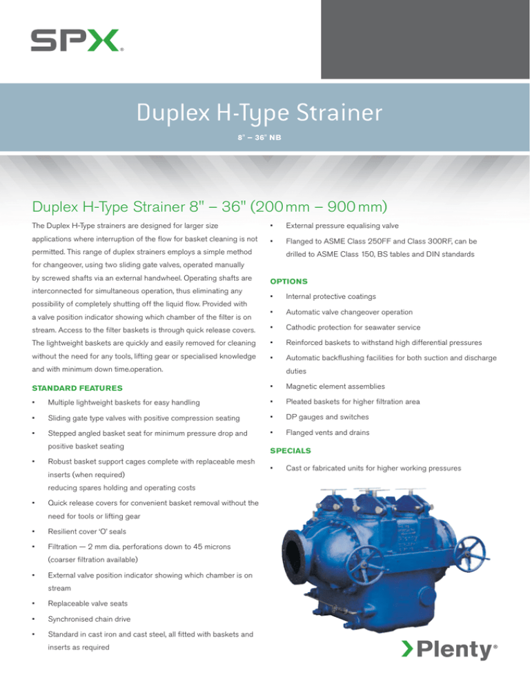
Duplex H-Type Strainer 8" – 36" NB Duplex H-Type Strainer 8" – 36" (200 mm – 900 mm) The Duplex H-Type strainers are designed for larger size • External pressure equalising valve applications where interruption of the flow for basket cleaning is not • Flanged to ASME Class 250FF and Class 300RF, can be permitted. This range of duplex strainers employs a simple method drilled to ASME Class 150, BS tables and DIN standards for changeover, using two sliding gate valves, operated manually by screwed shafts via an external handwheel. Operating shafts are interconnected for simultaneous operation, thus eliminating any Options • Internal protective coatings • Automatic valve changeover operation stream. Access to the filter baskets is through quick release covers. • Cathodic protection for seawater service The lightweight baskets are quickly and easily removed for cleaning • Reinforced baskets to withstand high differential pressures without the need for any tools, lifting gear or specialised knowledge • Automatic backflushing facilities for both suction and discharge possibility of completely shutting off the liquid flow. Provided with a valve position indicator showing which chamber of the filter is on and with minimum down time.operation. duties Standard Features • Magnetic element assemblies • Multiple lightweight baskets for easy handling • Pleated baskets for higher filtration area • Sliding gate type valves with positive compression seating • DP gauges and switches • Stepped angled basket seat for minimum pressure drop and • Flanged vents and drains positive basket seating • Robust basket support cages complete with replaceable mesh inserts (when required) reducing spares holding and operating costs • Quick release covers for convenient basket removal without the need for tools or lifting gear • Resilient cover ‘O’ seals • Filtration — 2 mm dia. perforations down to 45 microns (coarser filtration available) • External valve position indicator showing which chamber is on stream • Replaceable valve seats • Synchronised chain drive • Standard in cast iron and cast steel, all fitted with baskets and inserts as required SPECIALS • Cast or fabricated units for higher working pressures Design Data Ca s t I r on B S 14 5 2 GR 2 2 0 Ca s t S t e e l ASTM A 2 16 WC B F l a n g e R at i n g Design Pr e ssu r e Wo r k i n g T e m p F l a n g e R at i n g Design Pr e ssu r e Wo r k i n g T e m p A N SI 2 5 0 F F 10 . 3 B ARG ( 15 0 p s i g ) @ 38°C 0 ° C - 10 0 ° C A N SI 3 0 0 R F 2 0 B ARG ( 3 0 0 p s i g ) @ 38°C 0 ° C - 10 0 ° C standard internals S e rvice M at e r i a l s Va lv e s S hafts Va lv e S e at s D r ive N uts Ba s k e t Oi l Ca s t I r on B S 14 5 2 ~ 2 6 0 M i ld Ste e l B S 970 ~ 070 M 2 0 Ca s t I r on B S 14 5 2 ~ 2 6 0 Ca s t I r on B S 14 5 2 ~ 2 6 0 M i l d S t e e l B S 970 ~ 070 M 2 0 o r S ta i nl e s s S t e e l AISI 3 16 L Fr e s h Wat e r Ca s t I r on B S 14 5 2 ~ 2 6 0 S ta i nl e s s S t e e l B S 970 ~ 3 16 S 16 Ca s t I r on B S 14 5 2 ~ 2 6 0 Ca s t I r on B S 14 5 2 ~ 2 6 0 S ta i nl e s s S t e e l AISI 3 16 L S e a Wat e r G u n m e ta l B S 14 0 0 LG 4 S ta i nl e s s S t e e l B S 970 ~ 3 16 S 16 G u n m e ta l B S 14 0 0 LG 4 G u n m e ta l B S 14 0 0 LG 4 S ta i nl e s s S t e e l AISI 3 16 L o r Mon e l 4 0 0 Dimensions Size in mm Mo d e l No. N o . of Bas k ets A mm B mm C mm D mm E mm F mm G r o s s Ba s k e t Ar ea (pe r Cham b e r) cm² We ig ht lb kg 8 200 H N-8 2 10 0 0 419 902 238 568 692 3225 275 6 12 5 0 10 250 HS - 10 2 10 8 9 6 10 1112 4 47 606 738 5 16 0 3086 14 0 0 10 250 H L - 10 4 15 0 2 4 57 10 67 451 6 19 838 74 8 5 4960 2250 12 300 H N - 12 4 15 0 2 4 57 10 67 451 6 19 838 74 8 5 4960 2250 2250 14 350 HS - 14 4 15 0 2 4 57 10 67 451 6 19 838 74 8 5 4960 14 350 H L - 14 4 174 3 78 1 147 3 76 9 76 2 10 67 12 9 0 5 10 3 8 4 47 10 16 400 H N - 16 4 174 3 78 1 147 3 76 9 76 2 10 67 12 9 0 5 10 3 8 4 47 10 18 450 H N - 18 4 174 3 78 1 147 3 76 9 76 2 10 67 12 9 0 5 10 3 8 4 47 10 20 500 HS - 2 0 4 174 3 78 1 147 3 76 9 76 2 10 67 12 9 0 5 10 3 8 4 47 10 20 500 H L-20 8 2 410 870 16 3 5 830 12 4 0 15 6 5 25805 19 6 2 1 8900 24 600 HS - 2 4 8 2 410 870 16 3 5 830 12 4 0 15 6 5 25805 19 6 2 1 8900 24 600 H L-24 12 2600 870 170 0 12 2 0 15 2 5 18 0 0 3 87 10 2 0 6 57 9 370 28 70 0 H N-28 12 2600 870 170 0 12 2 0 15 2 5 18 0 0 3 87 10 2 0 6 57 9 370 30 75 0 H N-30 12 2600 870 170 0 12 2 0 15 2 5 18 0 0 3 87 10 2 0 6 57 9 370 32 800 H N-32 12 2600 870 170 0 12 2 0 15 2 5 18 0 0 3 87 10 2 0 6 57 9 370 36 900 H N-36 D e ta i l s on A p p l i cat i on Approximate dimensions only. Tolerance: Plus or Minus 3 mm SPX Flow Technology, SPX International Ltd, Hambridge Road, Newbury, Berkshire RG14 5TR Phone: +44 1635 42363 Fax: +44 1635 49758 E-Mail: plentyfilters@spx.com For more information about our worldwide locations, approvals, certifications, and local representatives, please visit www.plentyfiltration.net SPX reserves the right to incorporate our latest design and material changes without notice or obligations. Design features, materials of construction and dimensional data, as described in this bulletin, are provided for your information only and should not be relied upon unless confirmed in writing. Please contact your local sales representative for product availability in your region. For more information visit www.spx.com. “The green “>” is a trademark of SPX Corporation, Inc.” Issued: PF-40.00 -1- EN - 03/2013 COPYRIGHT © 2013 SPX Corporation


