Duct Heater Sample Specification
advertisement

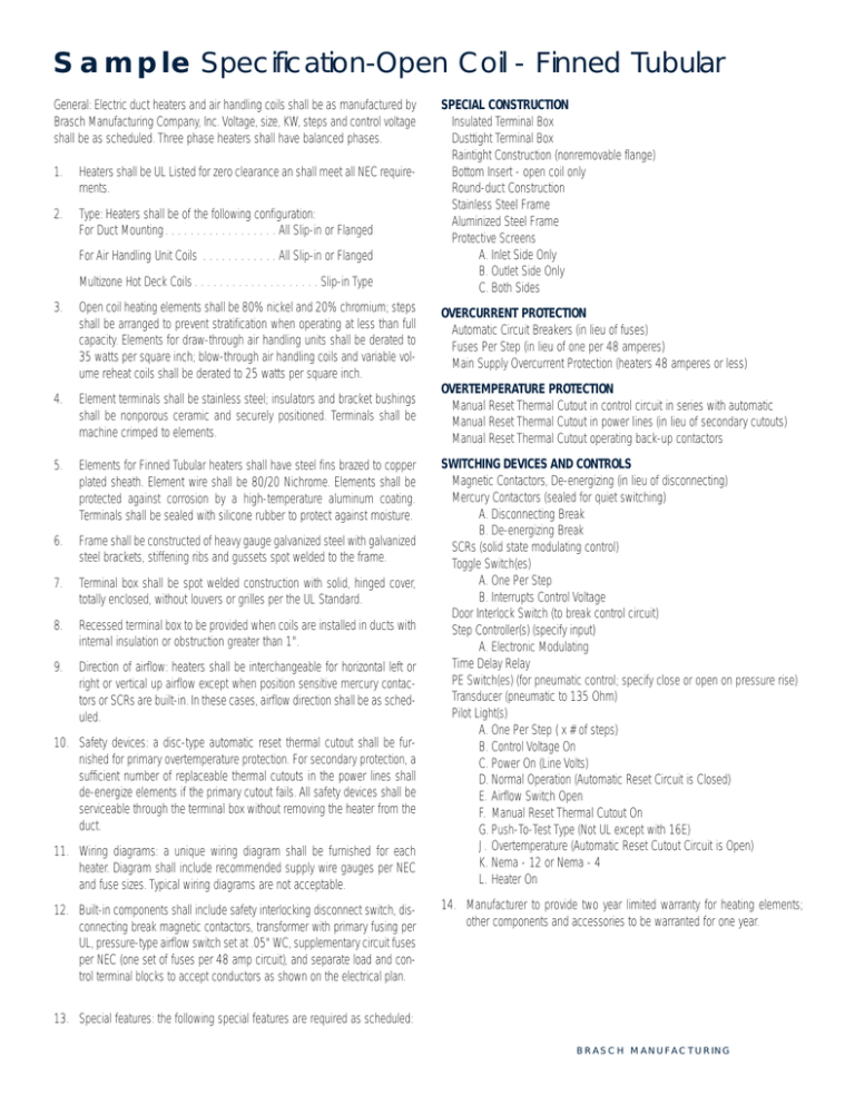
Sample Specification-Open Coil - Finned Tubular General: Electric duct heaters and air handling coils shall be as manufactured by Brasch Manufacturing Company, Inc. Voltage, size, KW, steps and control voltage shall be as scheduled. Three phase heaters shall have balanced phases. 1. Heaters shall be UL Listed for zero clearance an shall meet all NEC requirements. 2. Type: Heaters shall be of the following configuration: For Duct Mounting . . . . . . . . . . . . . . . . . . All Slip-in or Flanged For Air Handling Unit Coils . . . . . . . . . . . . All Slip-in or Flanged Multizone Hot Deck Coils . . . . . . . . . . . . . . . . . . . . Slip-in Type SPECIAL CONSTRUCTION • Insulated Terminal Box • Dusttight Terminal Box • Raintight Construction (nonremovable flange) • Bottom Insert - open coil only • Round-duct Construction • Stainless Steel Frame • Aluminized Steel Frame • Protective Screens A. Inlet Side Only B. Outlet Side Only C. Both Sides 3. Open coil heating elements shall be 80% nickel and 20% chromium; steps shall be arranged to prevent stratification when operating at less than full capacity. Elements for draw-through air handling units shall be derated to 35 watts per square inch; blow-through air handling coils and variable volume reheat coils shall be derated to 25 watts per square inch. OVERCURRENT PROTECTION • Automatic Circuit Breakers (in lieu of fuses) • Fuses Per Step (in lieu of one per 48 amperes) • Main Supply Overcurrent Protection (heaters 48 amperes or less) 4. Element terminals shall be stainless steel; insulators and bracket bushings shall be nonporous ceramic and securely positioned. Terminals shall be machine crimped to elements. OVERTEMPERATURE PROTECTION • Manual Reset Thermal Cutout in control circuit in series with automatic • Manual Reset Thermal Cutout in power lines (in lieu of secondary cutouts) • Manual Reset Thermal Cutout operating back-up contactors 5. Elements for Finned Tubular heaters shall have steel fins brazed to copper plated sheath. Element wire shall be 80/20 Nichrome. Elements shall be protected against corrosion by a high-temperature aluminum coating. Terminals shall be sealed with silicone rubber to protect against moisture. 6. Frame shall be constructed of heavy gauge galvanized steel with galvanized steel brackets, stiffening ribs and gussets spot welded to the frame. 7. Terminal box shall be spot welded construction with solid, hinged cover, totally enclosed, without louvers or grilles per the UL Standard. 8. Recessed terminal box to be provided when coils are installed in ducts with internal insulation or obstruction greater than 1". 9. Direction of airflow: heaters shall be interchangeable for horizontal left or right or vertical up airflow except when position sensitive mercury contactors or SCRs are built-in. In these cases, airflow direction shall be as scheduled. 10. Safety devices: a disc-type automatic reset thermal cutout shall be furnished for primary overtemperature protection. For secondary protection, a sufficient number of replaceable thermal cutouts in the power lines shall de-energize elements if the primary cutout fails. All safety devices shall be serviceable through the terminal box without removing the heater from the duct. 11. Wiring diagrams: a unique wiring diagram shall be furnished for each heater. Diagram shall include recommended supply wire gauges per NEC and fuse sizes. Typical wiring diagrams are not acceptable. 12. Built-in components shall include safety interlocking disconnect switch, disconnecting break magnetic contactors, transformer with primary fusing per UL, pressure-type airflow switch set at .05" WC, supplementary circuit fuses per NEC (one set of fuses per 48 amp circuit), and separate load and control terminal blocks to accept conductors as shown on the electrical plan. SWITCHING DEVICES AND CONTROLS • Magnetic Contactors, De-energizing (in lieu of disconnecting) • Mercury Contactors (sealed for quiet switching) A. Disconnecting Break B. De-energizing Break • SCRs (solid state modulating control) • Toggle Switch(es) A. One Per Step B. Interrupts Control Voltage • Door Interlock Switch (to break control circuit) • Step Controller(s) (specify input) A. Electronic Modulating • Time Delay Relay • PE Switch(es) (for pneumatic control; specify close or open on pressure rise) • Transducer (pneumatic to 135 Ohm) • Pilot Light(s) A. One Per Step ( x # of steps) B. Control Voltage On C. Power On (Line Volts) D. Normal Operation (Automatic Reset Circuit is Closed) E. Airflow Switch Open F. Manual Reset Thermal Cutout On G. Push-To-Test Type (Not UL except with 16E) J. Overtemperature (Automatic Reset Cutout Circuit is Open) K. Nema - 12 or Nema - 4 L. Heater On 14. Manufacturer to provide two year limited warranty for heating elements; other components and accessories to be warranted for one year. 13. Special features: the following special features are required as scheduled: BRASCH MANUFACTURING

