Lab session 2: Modified low-pass and high
advertisement
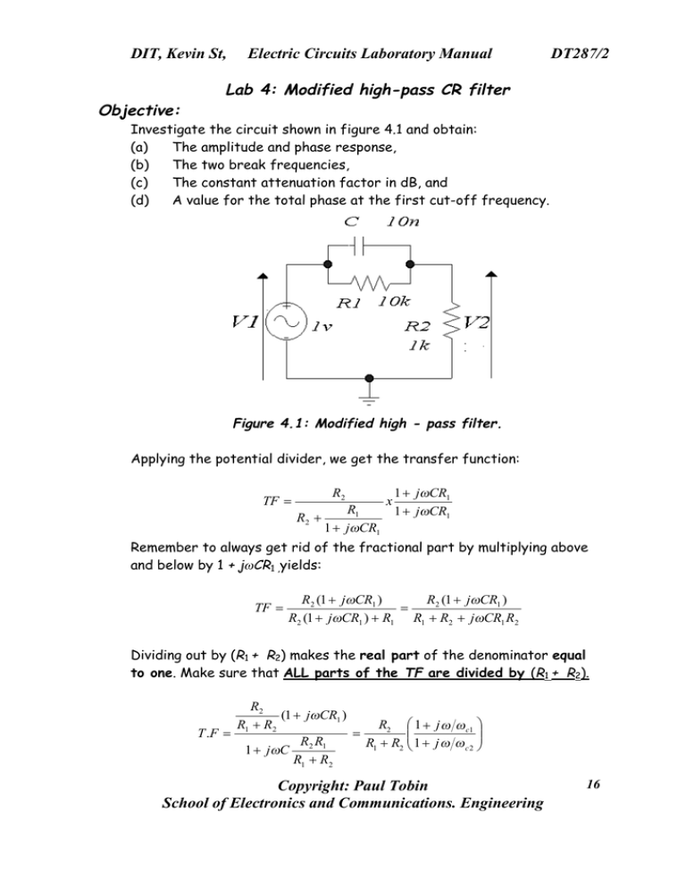
DIT, Kevin St, Objective: Electric Circuits Laboratory Manual DT287/2 Lab 4: Modified high-pass CR filter Investigate the circuit shown in figure 4.1 and obtain: (a) The amplitude and phase response, (b) The two break frequencies, (c) The constant attenuation factor in dB, and (d) A value for the total phase at the first cut-off frequency. Figure 4.1: Modified high - pass filter. Applying the potential divider, we get the transfer function: R2 TF = R2 + R1 1 + jωCR1 x 1 + jωCR1 1 + jωCR1 Remember to always get rid of the fractional part by multiplying above and below by 1 + jωCR1 ,yields: TF = R2 (1 + jωCR1 ) R2 (1 + jωCR1 ) = R2 (1 + jωCR1 ) + R1 R1 + R2 + jωCR1 R2 Dividing out by (R1 + R2) makes the real part of the denominator equal to one. Make sure that ALL parts of the TF are divided by (R1 + R2). R2 (1 + jωCR1 ) R1 + R2 R2 1 + j ω ω c1 T .F = = R2 R1 R1 + R2 1 + j ω ω c 2 1 + jωC R1 + R2 Copyright: Paul Tobin School of Electronics and Communications. Engineering 16 DIT, Kevin St, Electric Circuits Laboratory Manual DT287/2 The magnitude of the transfer function is: TF = R2 R1 + R2 1+ ( 1+ ( ω 2 ) ω c1 ω 2 ) ωc 2 ∠[tan −1 ( ω ω ) − tan −1 ( )] ω c1 ωc2 The cut-off frequencies are calculated for your circuit values f c1 = 1 = ?Hz 2πCR1 f c2 = 1 = ?Hz R1 R2 2πC R1 + R2 And Figure 4.2: Modified high-pass filter phase and amplitude response. Work out the value of the constant attenuation factor –20log ( R2 ). R1 + R2 Work out a value for the phase at the cut-frequency, ωc1 and compare this value on the phase response. Measure the maximum phase value. Save all gif files, responses, schematic, etc, write up your final filter report( i.e. the first four labs), print and submit. Copyright: Paul Tobin School of Electronics and Communications. Engineering 17
