83.214.xx06.3
83.210.xx81.3/ ...xx89.3
xx.xxx.xxxx.x
Wieland Electric GmbH
Brennerstraße 10-14
96052 Bamberg
Ph.: +49 (951) 9324-0
Fax: +49 (951) 9324-198
Internet: www.wieland-electric.com
E-mail: info@wieland-electric.com
podis MOT RA C 3I/RS485 SEW
ENGAssembly instructions
AS-i field distributor on energy bus
A. Important information - please read carefully
This addendum describes the assembly of the podis MOT RA C and its connection to
the energy bus. Please observe the warnings and notes at all times.
CAUTION
• All electrical installations and connections may be performed only by trained
electricians!
• The applicable safety and accident prevention regulations must be observed!
• The connectors may never be connected or disconnected under load!
• Before opening and removing the electronics cover, all cables must be de-energized.
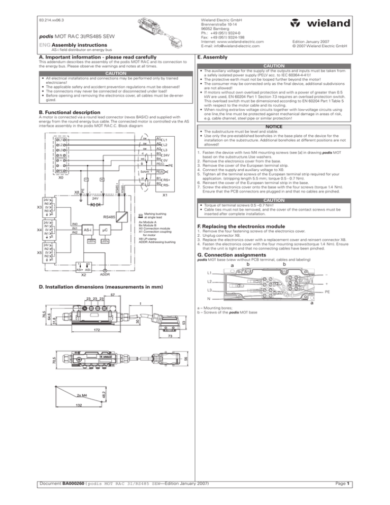
B. Functional description
A motor is connected via a round lead connector (revos BASIC) and supplied with
energy from the round energy bus cable. The connected motor is controlled via the AS
interface assembly in the podis MOT RA C.C. Block diagram
L1
L2
L3
N
+
sw
A1
sw
A2
sw
A3
rt
B3
ws
B4
PE
24V
IN0
X3 0V
IN0
1
2
3
4
5
24V
IN1
1
2
3
4
5
X4 0V
IN1
24V
IN2
X5 0V
IN2
RS485 -
RS485 +
+
-
X8
PE
X0
LED's
1
2
3
4
5
24V
or
B1
gn
B2
PE
RS+
RS-
X1
CAUTION
• The auxiliary voltage for the supply of the outputs and inputs must be taken from
a safely isolated power supply (PELV acc. to IEC 60364-4-41)!
• The protective earth must not be looped further beyond the motor!
• The consumer may be connected only as the final device, additional subdivisions
are not allowed!
• If motors without own overload protection and with a power of greater than 0.5
kW are used, EN 60204 Part 1 Section 7.3 requires an overload protection switch.
This overload switch must be dimensioned according to EN 60204 Part 1 Table 5
with respect to the motor cable and its routing.
• When routing extra-low voltage circuits together with low-voltage circuits using
one line,the line must be protected against mechanical damage in areas of risk,
e.g. cable channel, steel pipe or similar protection!
NOTICE
1. Fasten the device with two M4 mounting screws (see [a] in drawing podis MOT
base) on the substructure.Use washers.
2. Remove the electronics cover from the base.
3. Remove the cover of the European terminal strip.
4. Connect the supply and auxiliary voltage to X0.
5. Tighten all the terminal screws of the European terminal strip required for your
application. (stripping length 5.5 mm; torque 0.5 - 0.7 Nm).
6. Reinsert the cover of the European terminal strip in the base.
7. Screw the electronics cover onto the base with the four screws (torque 1.4 Nm).
Ensure that the PCB connectors are plugged in and that no cables are pinched.
CAUTION
RS485
AS-i
L3
PE(A)
24V
IN0
IN1
IN2
L2
Schirm
E. Assembly
• The substructure must be level and stable.
• Use only the pre-established boreholes in the base plate of the device for the
installation on the substructure. Additional boreholes at different positions are not
allowed!
L1
0V
PE(C)
Edition January 2007
© 2007 Wieland Electric GmbH
µC
LED's
xx
Marking bushing
at single lead
Ax Module A
Bx Module B
X0 Connection module
X1 Connection coupling
for motor
X8 LP-clamp
ADDR Addressing bushing
• Torque of terminal screws 0.5 –0.7 Nm!
• Cable ties must not be removed, and the cover of the contact screws must be
inserted after complete installation.
F. Replacing the electronics module
1.
2.
3.
4.
Remove the four fastening screws of the electronics cover.
Unplug connector X8.
Replace the electronics cover with a replacement cover and reinsert connector X8.
Fasten the electronics cover with the four mounting screws(torque 1.4 Nm). Ensure
that the unit is tight and that no connecting cables have been pinched.
G. Connection assignments
1
podis MOT base (view without PCB terminal, cables and labeling)
3
�
ASI+ ASI-
X2
ADDR
D. Installation dimensions (measurements in mm)
�
�
L1
−
L2
+
L3
N
PE
�
a – Mounting bores;
b – Screws of the podis MOT base
Document BA000260 ( podis MOT RA C 3I/RS485 SEW—Edition January 2007)
Page H. Technical data
Motor connection coupling X1
orange
AC input
Input voltage Vsupply
Supply frequency input
AC output
Output voltage
Output current per phase
Output frequency
Connection (X1) to motor
black
green
black
red (+)
white (-)
negro
Border
Cable shielding
with wires
RS+, RS- and 0V,
24V on-hook
DC inputfor MOVIMOT electronics
supply, 24 V external
Input voltage
Power consumption for each MOVIMOT
AS interface
AS-i specification
green-yellow
Module C
Module A
Module B
Module
PIN
A
1
2
3
1
2
3
4
B
Designation
Meaning
L1
L2
L3
RS+
RS+
−
Motor lead voltage U
Motor lead voltage V
Motor lead voltage W
RS485 signal voltage +
RS485 signal voltage 24 VDC of external voltage (from 24-V power supply)
0 V of external voltage (from 24-V power supply)
AS interface connection X2 (M12)
(view from outside onto plug contacts)
Pin
Brief description
1
3
2, 4, 5
AS interface +
AS interface −
Comments
Contacts not fitted
Digital inputs X3, X4, X5 (M12)
(view from outside onto socket contacts)
�
�
�
Pin
Brief description
Comments
1
2/42
3
5
24 V
INx
0V
Ground
24-V sensor supply1
Digital inputs
0V Sensor-Versorgung1
Equipotential bonding
The digital inputs at X3, X4 and X5 are supplied from the
AS interface
2
Pin 2 and 4 are internally bridged
1
�
�
CAUTION
To be able to ensure enclosure IP 65, all unused inputs or outputs must be fitted
with protection covers!
Meaning of LEDs on the housing cover
����������
No.
Color
Designation
Meaning
1
Green
AS-i power
AS-i power ok.
2
Red
AS-i fault
Fault of AS-i
3
Yellow
IN 0
Input M12
IN0
���
4
Yellow
IN 1
Input M12
IN1
���
5
Yellow
IN 2
Input M12
IN2
����
6
Yellow
M ok
Motor is operational
IN3
�����
7
Yellow
M fwd
CW rotation of motor
�����
8
Yellow
M rev
CCW rotation of motor
9
Yellow
M RS485
RS485
10
Red
M fault
Fault of motor
�������
�������
AS-i voltage, min.
Current consumption from AS-i
Addressing option
Digital inputs
Digital inputs (via AS-i)
Input current
Input resistance
Supply current of initiators
Signal level VHIGH / VLOW
Scan time
General data
Environmental conditions (overall device)
Overvoltage category
Fire behavior of contact carriers
Temperature ranges
– Operating environment
– Storage/transport
Vibration
Air humidity
Enclosure
Protection class
Mounting position
Dimensions
Vsupply (input voltage)
max. 16 A (observe line fusing!)
50 Hz ±10% (45 Hz...55 Hz)
Hybrid cable max. 5 m (RS485 interface,
integrated bus termination;24 V supply voltage, damping diode; L1, L2, L3 and PE)
24 VDC ± 20 % (19.2 V…28.8 V)
approx. 0.2 W (without inputs and outputs)
V2.11, single slave, profile S7.4, identification 74F0
31
max. 30 cm tap line per module + 100 m
AS interface line
26.5 V
max. 280 mA
DC socket 1.3 mm
3 (IN0, IN1, IN2)
typ. 5 mA
typ. 5 kΩ
max. 50 mA for each initiator
+15 V…+31.5 V/ −3 V…+5 V
approx. 5 ms
Industrial atmosphere
3
min. UL94V2
0…50 °C
−25 °C…60 °C/ −25 °C…+70 °C
IEC 60721-3-3 Class 3M6
100 %, non-condensing
IP 65 acc. to EN 60529
Class 1 acc. to 60536
any (preferablyhorizontal wall mounting)
see under "D. Installation dimensions"
I. Ordering information
Accessories
• AS-i tap line 30 cm
• AS-i branching profile line M12
• AS-i hand-held PPG 1
• Programming cable AS-i 1.5 m
Spare parts
• Electronics module
• European terminal strip 6ETS 3 pins
• European terminal strip 6ETS 4 pins
• Motor cable, complete
83.209.2203.0
83.209.2201.0
83.209.2204.1
83.209.2205.0
83.209.2102.2
99.360.4379.9
99.361.4379.9
Upon request
I/O bit
���
����������
Number of addressable slaves
Line length
230/400 VAC
50 Hz ±10 % (45 Hz…55 Hz)
Operating indicators
Check the device for safe functioning. The operating state of the AS-i slave is indicated
as follows by LED 1 and 2:
No.
LED
Status
Meaning
1
2
Green
Red
constantly on
constantly on
2
Red
flashing
Voltage supply ok.
Communication error at AS interface, slave
does not participate in normal data traffic (e.g.
slave address 0)
Periphery error, e.g. short circuit of AS-i
voltage
© 2007 Wieland Electric GmbH. All rights reserved. Third-party products are used without reference to patent rights. For this reason, the existence of such rights should not
be excluded. Any type of changes to the hardware or software of WIELAND products
results in the exclusion of liability by WIELAND ELECTRIC GmbH.
Document BA000260 ( podis MOT RA C 3I/RS485 SEW—Edition January 2007)
Page


