ATSD Series
Auxilary Transfer Switch
Catalog Number
FEATURES
Application
The ATSD auxiliary transfer switch works in conjunction with
an emergency lighting inverter or an auxiliary generator to
power switched or dimmed emergency lighting fixtures up to
3A. The auxiliary transfer senses the loss of normal power and
bypasses the switch or dimmer, transferring the lighting load
to a designated emergency power source, regardless of the
switch or dimmer position. Recommended applications include:
auditoriums, classrooms, or any other location with generator or
inverter-supplied emergency lighting.
Construction
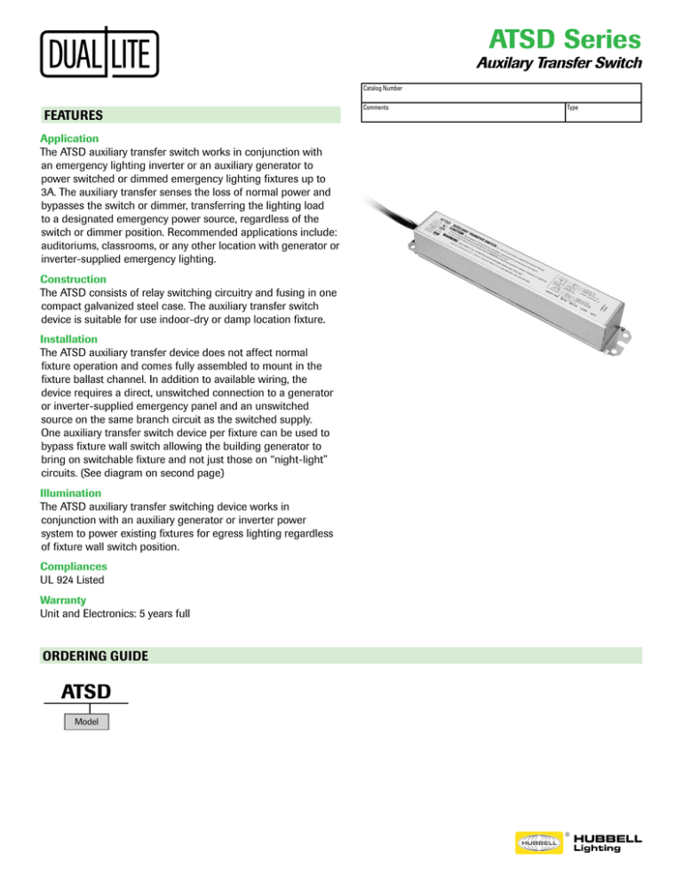
The ATSD consists of relay switching circuitry and fusing in one
compact galvanized steel case. The auxiliary transfer switch
device is suitable for use indoor-dry or damp location fixture.
Installation
The ATSD auxiliary transfer device does not affect normal
fixture operation and comes fully assembled to mount in the
fixture ballast channel. In addition to available wiring, the
device requires a direct, unswitched connection to a generator
or inverter-supplied emergency panel and an unswitched
source on the same branch circuit as the switched supply.
One auxiliary transfer switch device per fixture can be used to
bypass fixture wall switch allowing the building generator to
bring on switchable fixture and not just those on “night-light”
circuits. (See diagram on second page)
Illumination
The ATSD auxiliary transfer switching device works in
conjunction with an auxiliary generator or inverter power
system to power existing fixtures for egress lighting regardless
of fixture wall switch position.
Compliances
UL 924 Listed
Warranty
Unit and Electronics: 5 years full
ORDERING GUIDE
ATSD
Model
Comments
Type
ATSD Series
Auxilary Transfer Switch
SPECIFICATIONS
Electronics
The ATSD auxiliary transfer switching device senses the loss of normal power and switches the AC ballast input power
connection to an unswitched, generator or inverter-supplied lighting circuit. No routine maintenance is required to keep the
ATSD functional; however, like other life safety unit equipment, it should be checked periodically to ensure that it is working
properly. Operates at a dual input voltage of 120 or 277VAC.
Standard Features Include:
• Easy installation inside of ballast channel
• Compatible with all lamp types
• Battery case made of galvanized steel
• Low power consumption
• Maximum power consumption: 1.6 Watts
Operating Temperature Range:
Standard: 32˚F to 122˚F (0˚C to 50˚C)
DIMENSIONS
8.0”
20.4 cm
1.18”
3.0 cm
1.18”
3.0 cm
WIRING DIAGRAM
LIGHTING
LOAD UP
TO 3A
Web: www.dual-lite.com • Tech Support: (866)-313-3909
701 Millennium Blvd. • Greenville, SC 29607 U.S.A.
Copyright © Dual-Lite, a division of Hubbell Lighting, Inc., All Rights Reserved
Specifications subject to change without notice. • Printed in U.S.A.
0603164 F 12/15

