Typical installations
for wound-rotor
starting
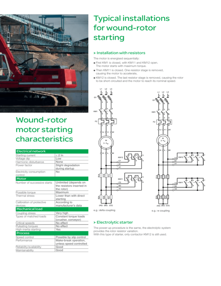
> Installation with resistors
The motor is energised sequentially:
irst KM1 is closed, with KM11 and KM12 open.
F
The motor starts with maximum torque.
hen KM11 is closed. One resistor stage is removed,
T
causing the motor to accelerate,
M12 is closed. The last resistor stage is removed, causing the rotor
K
to be short-circuited and the motor to reach its nominal speed.
L2
L1
L3
3
1
Q1
2
4
6
1
3
5
2
4
6
1
3
5
2
Calibration of protective
devices
Mechanical load
Coupling stress
Types of matched loads
Critical speeds
Pulsating torques
High-inertia starting
Process
Speed control
Performance
Reliability/availability
Maintainability
4
2
4
6
1
3
5
2
4
6
1
3
5
6
2
4
6
V
W
L
M
U
U
V
W
M
3
M
3
K
≤2 In
Low
None
Slight degradation
during startup
No
L
M
KM12
C1
Possible by slip control
Make-break operation,
unless speed controlled
Good
Good
5
2
4
6
C1 KM12
B1
1
3
5
7
2
4
6
8
1
3
5
7
2
4
6
8
A1
C3
5
2
4
6
R1C
3
R1B
1
R1A
R1C
C3 KM11
(A2) (B2) (C2)
e.g.: delta coupling
R2C
A3
R2B
B3
A3
R2C
B3
R2A
R1B
R1A
Very high
Constant torque loads
(crusher, conveyor)
No effect
No effect
Yes
3
A1
KM11
Unlimited (depends on
the resistors inserted in
the rotor)
Maximum
Lower than with direct
starting
According to
manufacturer's data
1
B1
R2B
Possible torque
Thermal stress
5
K
Motor
Number of successive starts
3
F2
R2A
Electricity consumption
control
KM1
F2
Electrical network
Starting current
Voltage dip
Harmonic disturbance
Power factor
L3
1
Q1
KM1
Wound-rotor
motor starting
characteristics
L2
L1
5
(A2) (B2) (C2)
e.g.: w coupling
> Electrolytic starter
The power-up procedure is the same, the electrolytic system
provides the rotor resistor variation.
With this type of starter, only contactor KM12 is still used.
To find out more about
TeSys B contactors
General documentation:
> Refer to the variable-composition contactor catalogue and the other
data sheets on TeSys B contactors.
> Download the "Soft-CustomerB" software.
Schneider Electric Industries SAS
35, rue Joseph Monier
CS 30323
F- 92506 Rueil Malmaison Cedex
RCS Nanterre 954 503 439
Capital social 896 313 776
www.schneider-electric.com
EDCED110014EN
As standards, specifications and designs change from time to time, please ask for confirmation of
the information given in this publication.
Printed on ecological paper
Publication: Schneider Electric
Design-Layout: SEDOC
Printing: Altavia connexion
04-2012
© 2012- Schneider Electric - All rights reserved.
www.schneider-electric.com
TeSys B bar-mounted contactors
Starting high-power
wound-rotor AC motors
Soft-start your AC motors
(> 400 kW) gradually without
reducing the torque
Soft-starting wound-rotor AC motors involves removing rotor resistors until the rotor
is short-circuited.
This makes it possible to start the motor with the maximum torque (fig. 1a-2a),
whilst reducing the inrush current (fig. 1b-2b).
This type of motor is found in lifting applications, as well as in crushers, mixers, centrifuges or
even conveyors and any Medium-Voltage motor application where it is necessary to limit the
starting current.
It is used in industrial facilities, for example iron and steel, naval, water and water treatment
installations, as well as harbour infrastructures, mines, quarries and paper mills.
3-stroke starting
4-stroke starting
Torque
Torque
Current
Current
2.5
Secon
d-
Sec
o
nd-
3
ew
it h
ou
tr
stro
ke
t
2
es
is
1.5
to
r
orq
ue
6
ithout resistor
ue w
Torq
rque
e to
ro k
ue
orq
et
rok
-st
5
4
oke
tor
qu
e
Torq
u
Third
-
st
1
6
Se
co
nd
Firs
t-st
r
s to r
t resi
1.5
u
tho
wi
ue
orq
et
ok
str
2
7
2.5
7
rque
To
First-str
o
ke to
rqu
e
1
1
Speed
0
fig.1a
0.25
0.50
0.75
1
4
First-strok
e
0
torqu
0.5
e
1
Speed
0.25
0.50
0.75
fig.1b
1
Speed
0
fig.2a
0.25
0.50
0.75
1
Tor
que
wit
ho
ut
res
ist
Thir
d-st
roke
3
2
2
0.5
5
torq
Seco
nd-st
roke
First-stroke t
or
0
or
ue
torq
ue
que
Speed
0.25
0.50
0.75
fig.2b
Note: this starting method allows the motor torque and the starting current required at each stage to be defined according
to the values of the rotor resistors.
> Provides a very good torque/current ratio at startup (lifting) to optimise the dimensioning of the electrical
installation and avoid in-line voltage drops.
> Makes it possible to adjust the starting torque and current.
> Avoids power failures during the startup period.
> In accordance with IEC 60947-4-1, the contactor utilisation categories for this type of starting are AC1
for the rotor and AC3 for the stator.
1
Our TeSys B range of bar-mounted
Designed to control AC motors from 400 kW to 900 kW, for all v
TeSys B range of bar-mounted contactors
Line contactor KM1
(stator)
Rotor resistor short-circuiting contactors*
KM11, KM12
AC3 utilisation category.
From the motor torque and starting current required for each stage
according to the application and depending on the type of contact
coupling:
Coupling : 4 contacts
Coupling: 2 contacts
Star coupling: 3 contacts
Delta coupling: 3 contacts
Depending on the characteristics of the motor
to be supplied, choose the range:
Line contactor KM1 (stator)
Motor
Power
Power factor
Rated voltage
Current frequency
Calculation to be
carried out
Rated current of
the contactor in
AC3*
Choose the range according to the rotor voltage:
* See table opposite
Rotor resistor short-circuiting contactors KM11, KM12
Rotor
Rotor voltage
Rotor steady state and
starting current
Calculation to be carried out
Resistance to be defined by the customer
* These contactors can be mounted on MV motors whose rotor voltage is less than 3000 V.
Selection table
Contactor
Line contactor KM1 (stator)
Motor (stator) supply voltage
690 V
1000 V
CV1B
CV3B, LC1B
Note : for motors less than 400 kW, choose TeSys F range.
Contactor
Rotor resistor short-circuiting
contactors KM11, KM12
Rotor voltage
< 2000 V
> 2000 V
TeSys F range or CV1B, CV3B, LC1B
Special construction (reinforced
insulation) CV1B, CV3B
The devices are designed to operate at an ambient temperature of 40°C. Current derating is required for higher temperatures.
contactors
voltages ≤ 1500 V for stators and 3000 V for rotors.
How to size the contactors?
Three-phase 4-pole motor (current values for power in kW)
Rated operating power (1)
Guideline values for rated operating currents at:
400 V
kW
500 V
690 V
A
A
A
400
690
552
400
500
850
680
493
560
950
760
551
630
1060
848
615
710
1190
952
690
800
1346
1076
780
900
1518
1214
880
1000
1673
1339
970
(1) Values in accordance with the IEC 60072-1 standard (at 50 Hz).
Note: The values given in this table are for information only, as they vary according to the type of motor, its polarity and the manufacturer.


