TrueAlarm Analog Sensing
UL, ULC, CSFM Listed; FM Approved;
MEA (NYC) Acceptance*
In-Duct Mounting of the 4098-9714
TrueAlarm Photoelectric Smoke Sensor
Features
Install the model 4098-9714 TrueAlarm analog
photoelectric sensor directly inside air ducts** :
Accommodates duct airflow from 0 to 4000 ft/min
(0 to 1220 m/min), providing HVAC duct smoke
sensing where sampling tube designs are not
appropriate (refer to specifications on page 4 for more
information)
For applications with controlled dust and humidity
Standard models are for rectangular ducts from 6”
(152 mm) square to 36” (914 mm) square
Optional adapters allow use with round ducts of 6”, 8”
(203 mm), 10” (254 mm) or 12” (305 mm) in diameter
TrueAlarm analog communications can be either
IDNet or MAPNET II format
Model 4098-9714 sensor is required and ordered
separately
Red alarm LED indicator in housing:
Visible through transparent housing cover
Pulsing indicates power-on, steady on indicates alarm
or trouble as indicated at the fire alarm control panel
Model 4098-9750 provides two-wire operation (no
relay output)
Model 4098-9751 provides a local relay:
Relay operation is programmable from fire alarm
control panel and is rated: 1 A @ 28 VDC, power
limited; or 1/2 A @ 120 VAC, non-power limited
24 VDC power is supplied by fire alarm system
(4-wire operation)
Options:
Adapters for 6”, 8”, 10” or 12” round ducts
Remote Test Station (2098-9806)
Remote LED Alarm Indicator (2098-9808)
UL listed to Standard 268A
** Please note that smoke detection in air ducts is
intended to notify of the presence of smoke in the duct.
It is not intended to, and will not, replace smoke
detection requirements for open areas or other non-duct
applications.
* This product has been approved by the California State Fire Marshal (CSFM) pursuant to
Section 13144.1 of the California Health and Safety Code. See CSFM Listing
3240-0026:220 for allowable values and/or conditions concerning material presented in this
document. It is subject to re-examination, revision, and possible cancellation. ULC listed
models are designated with a “C” suffix such as 4098-9750C. Accepted for use – City of New
York Department of Buildings – MEA35-93E. Additional listings may be applicable; contact
your local Simplex product supplier for the latest status. Listings and approvals under
Simplex Time Recorder Co. are the property of Tyco Fire Protection Products.
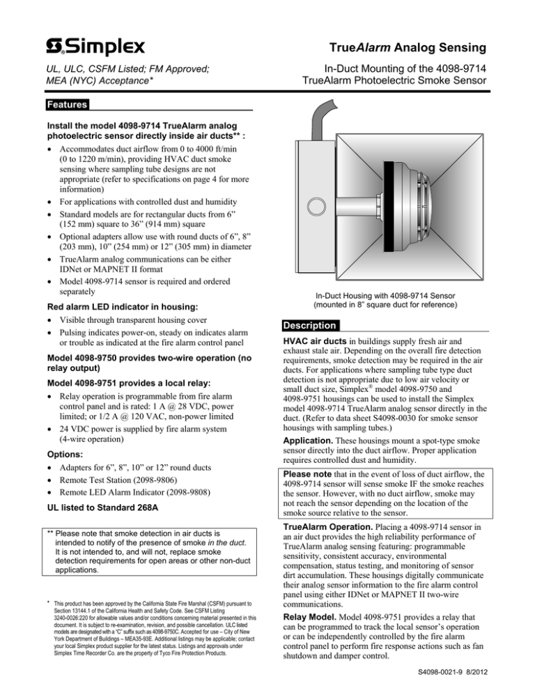
In-Duct Housing with 4098-9714 Sensor
(mounted in 8” square duct for reference)
Description
HVAC air ducts in buildings supply fresh air and
exhaust stale air. Depending on the overall fire detection
requirements, smoke detection may be required in the air
ducts. For applications where sampling tube type duct
detection is not appropriate due to low air velocity or
small duct size, Simplex® model 4098-9750 and
4098-9751 housings can be used to install the Simplex
model 4098-9714 TrueAlarm analog sensor directly in the
duct. (Refer to data sheet S4098-0030 for smoke sensor
housings with sampling tubes.)
Application. These housings mount a spot-type smoke
sensor directly into the duct airflow. Proper application
requires controlled dust and humidity.
Please note that in the event of loss of duct airflow, the
4098-9714 sensor will sense smoke IF the smoke reaches
the sensor. However, with no duct airflow, smoke may
not reach the sensor depending on the location of the
smoke source relative to the sensor.
TrueAlarm Operation. Placing a 4098-9714 sensor in
an air duct provides the high reliability performance of
TrueAlarm analog sensing featuring: programmable
sensitivity, consistent accuracy, environmental
compensation, status testing, and monitoring of sensor
dirt accumulation. These housings digitally communicate
their analog sensor information to the fire alarm control
panel using either IDNet or MAPNET II two-wire
communications.
Relay Model. Model 4098-9751 provides a relay that
can be programmed to track the local sensor’s operation
or can be independently controlled by the fire alarm
control panel to perform fire response actions such as fan
shutdown and damper control.
S4098-0021-9 8/2012
In-Duct Sensor Selection Chart
Model
4098-9750
Description
Compatibility
4098-9751
In-Duct Sensor Housing
with beige mounting box,
(requires 4098-9714 sensor)
4098-9714
Photoelectric Sensor Head
without relay
with relay
Simplex 4100ES, 4010ES, 4100U, 4010, 4020, 4100, 4120, and
2120 CDT configured for MAPNET II TrueAlarm communications
Simplex 4100ES, 4010ES, 4100U, 4010, 4020, 4100, and 4120
(not compatible with 2120 CDT)
Ordered separately, required for 4098-9750 or 4098-9751
In-Duct Sensor Options, ordered separately as required, compatible with both 4098-9750 and 4098-9751
4098-9819
4098-9824
4098-9852
4098-9853
2098-9806
2098-9808
Adapter for 6” (152 mm) round duct, beige
Adapter for 8” (203 mm) round duct, beige
Adapter for 10” (254 mm) round duct, beige
Adapter for 12” (305 mm) round duct, beige
Remote Test Station mounted on single gang stainless steel plate
Remote LED Alarm Indicator mounted on single gang stainless steel plate
Rectangular Duct Mounting Reference
In-Duct sensor access requires
wiring with flexible conduit
(supplied separately)
Sensor base
(supplied)
8 Inch square duct
(shown for reference)
External mounting box
7-1/4" H x 7-1/8" W x 2" D
(184 mm x 181 mm x 51 mm)
Sensor head
4098-9714
(ordered
separately)
Transparent housing cover
allows viewing of status LEDs
Gasket (supplied)
Gasket (supplied)
5-1/4"
(133 mm)
Mounting Notes for both Square and Round Duct Applications:
1.
2.
3.
4.
Reference drawings are shown mounted to the side of the duct. Where appropriate, top mounting may be
acceptable. Contact your local Simplex product supplier for assistance.
The 4098-9750 and 4098-9751 In-Duct assemblies include sensor base assembly, mounting box and cover, and
mounting gaskets. The 4098-9714 sensor head is ordered separately.
Templates are supplied for duct cutout size and location. Refer to installation instructions 574-711 for
additional information.
Adapters for 6”, 8”, 10”, or 12” round duct applications are ordered separately.
2
S4098-0021-9 8/2012
Round Duct Mounting Reference
In-Duct sensor access requires
wiring with flexible conduit
(supplied separately)
4098-9824
8" Adapter
Gasket
(supplied)
Gasket
(supplied)
External mounting box
7-1/4" H x 7-1/8" W x 2" D
(184 mm x 181 mm x 51 mm)
8 Inch air duct
(shown for reference)
Sensor head
4098-9714
(ordered separately)
Transparent housing cover
allows viewing of status LEDs
Sensor base
(supplied)
3/4"
(19 mm)
4-3/8"
(111 mm)
Remote Indicator Options
2098-9806, Remote Test Station (below), provides a
remote red LED status indicator and a remote test key
switch mounted on a single gang stainless steel plate.
Turning the test switch to “TEST” will initiate an alarm
and allow the resulting system responses to be verified.
2098-9808, Remote LED Alarm Indicator (below),
provides a remote Red LED status indicator mounted on a
single gang stainless steel plate.
ALARM
ALARM
TEST
NORM
2098-9808 Remote LED Alarm Indicator
2098-9806 Remote Test Station
Remote Indicator Mounting. Both the 2098-9806 and
2098-9808 Remote status indicators mount in standard
single gang boxes, 2” W x 3” H (51 mm x 76 mm) with a
minimum depth of 2”, supplied separately.
3
S4098-0021-9 8/2012
Location Reference
Duct Sensor Location Considerations:
1. Proper duct smoke detection location must ensure
adequate airflow within the duct housing.
2.
Ensure accessibility for test and service.
3.
Proper Locations: downstream side of filters to detect
fires in the filters; in return ducts, ahead of mixing
areas; upstream of air humidifier and cooling coil.
4.
Other locations may be required for proper duct
smoke detection depending on duct access, system
design, and duct airflow testing. Contact your local
Simplex product supplier for assistance.
Locations to Avoid:
1. Where dampers closed for comfort control would
interfere with airflow.
2. Next to outside air inlets (unless the intent is to
monitor smoke entry from that area).
3. In return air damper branch ducts and mixing areas
where airflow may be restricted.
Additional Information. Refer to NFPA 90A, Standard
for the Installation of Air Conditioning and Ventilating
Systems; NFPA 72, the National Fire Alarm and Signaling
Code; and the NEMA Guide for Proper Use of Smoke
Detectors in Duct Applications, and Installation Instructions
574-711.
In-Duct Sensor Location Reference
Exhaust
Damper
Sensor
OK
Return
Air
Exhaust
Do not locate
sensor here
Return air
damper
Supply
Air
Fresh
air
Do not locate
sensor here
Filter
bank
Sensor
OK
Specifications
0-4000 ft/min (0-1220 m/min) with a minimum sensor sensitivity of 3.0% per ft
0-2000 ft/min (0-610 m/min) with a minimum sensor sensitivity of 3.7% per ft
UL Listed Air Velocity Range
Data Communications
Remote LED Current
UL Listed Temperature Range
Operating Temperature Range
Humidity Range
Wiring Connections
Dimensions
NOTE: See
application
discussion
on page 1.
IDNet or MAPNET II format, auto-selected, 1 address per housing
0.6 mA, no impact to alarm current
32° to 100° F (0° to 38° C)
15° to 122° F (-9° to 50° C)
10% to 90% RH from 32 F to 122 F (0 C to +50 C)
Terminal blocks for wire size 18 to 14 AWG (0.82 mm2 to 2.08 mm2 )
Refer to round and square duct mounting diagrams
Relay Power (4098-9751 only)
Voltage
Standby Current
Alarm Current
Power Limited Contact Rating
Non-Power Limited Contact Rating
18 to 32 VDC
240 A @ 24 VDC
30 mA @ 24 VDC
Single form “C”, 1 A @ 28 VDC (for suppressed loads)
Single form “C”, 1/2 A @ 120 VAC, resistive (for suppressed loads)
TYCO, SIMPLEX, and the product names listed in this material are marks and/or registered marks. Unauthorized use is strictly prohibited. NFPA 72 and National Fire Alarm and
Signaling Code are trademarks of the National Fire Protection Association (NFPA).
Tyco Fire Protection Products • Westminster, MA • 01441-0001 • USA
www.simplexgrinnell.com
S4098-0021-9 8/2012
© 2012 Tyco Fire Protection Products. All rights reserved. All specifications and other information shown were current as of document revision date and are subject to change without notice.


