Digital TV Reception issues
advertisement

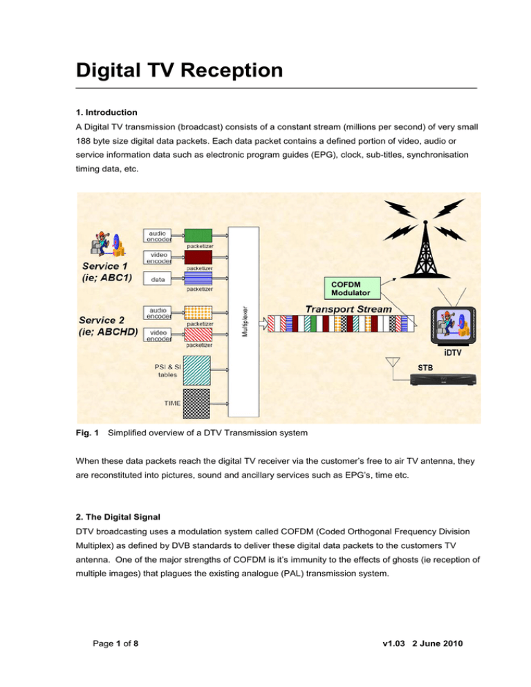
Digital TV Reception 1. Introduction A Digital TV transmission (broadcast) consists of a constant stream (millions per second) of very small 188 byte size digital data packets. Each data packet contains a defined portion of video, audio or service information data such as electronic program guides (EPG), clock, sub-titles, synchronisation timing data, etc. COFDM Modulator Fig. 1 Simplified overview of a DTV Transmission system When these data packets reach the digital TV receiver via the customer’s free to air TV antenna, they are reconstituted into pictures, sound and ancillary services such as EPG’s, time etc. 2. The Digital Signal DTV broadcasting uses a modulation system called COFDM (Coded Orthogonal Frequency Division Multiplex) as defined by DVB standards to deliver these digital data packets to the customers TV antenna. One of the major strengths of COFDM is it’s immunity to the effects of ghosts (ie reception of multiple images) that plagues the existing analogue (PAL) transmission system. Page 1 of 8 v1.03 2 June 2010 2. Electrical Interference and DTV signals The DVB-T (Digital Video Broadcasting – Terrestrial) broadcasting system used in Australia transmits very robust DTV signals, but digital TV data packets carried by COFDM are still subject to corruption and degradation (like all communication signals!) as they travel between the broadcaster’s transmission tower and the customer’s digital TV receiver. Electrical interference (commonly known as Impulse Noise) can corrupt many thousands of data packets. Depending on the nature of the corruption, some data packets are beyond the repair capabilities of the digital TV receiver. Corrupted data packets manifest themselves as picture break-up and or momentary audio dropouts. It also stands to reason that the further you are from the transmission tower, the weaker DTV signals become. Weak signals are also more susceptible to corruption by electrical noise and atmospherics. At some point, the DTV signal becomes so degraded as to become un-useable. Digital TV receivers contain a signal quality checker where video & audio is muted when the packet error count exceeds a prescribed limit. At this point a ‘No signal’, ‘Bad Signal’, ‘Check Antennal Connection’ etc error message will appear on the screen. 3. Common Sources of Electrical Interference a) Generally speaking, older style thermostat based / brush type motor appliances such as stoves, ovens, air conditioners, swimming pool pumps and associated automatic chlorine / acid feeders, mixers, blenders, dishwashers, washing machines, hair dryers, electric drills, circular saws etc. b) Cordless telephones and other household RF transmission devices c) Household light switches / power point switches d) Ignition based systems (ie; spark plugs / ignition coils) such as motor cars, motor bikes, lawn mowers, edge trimmers etc e) Natural sources such as a local or distant lighting storm 4. How does this interference reach the DTV set? Household interference is induced into the DTV normally via the customer’s antenna cable system and or poor / corroded antenna connectors especially those using saddle clamp type connections as commonly used in TV outlet sockets, antenna splitters etc.. Page 2 of 8 v1.03 2 June 2010 5. Typical DTV Reception Issues Item Reception Symptom Possible Cause(s) Diagnostic / Corrective Action(s) Using the TV’s built-in ‘DVB Signal Display’ feature, check and note signal strength & quality reading of the wanted channel Check to ensure the wanted DTV channel is broadcast in your region If you live in a unit or apartment using a Master TV Antenna (MATV) system, check to ensure it can distribute analogue AND DTV signals 1 Cannot receive or tune in a particular DTV channel Inadequate or poor signal If multiple RF input devices (VCR, DVD Recorder etc) are interconnected via RF loopthrough, disconnect RF loop-through connection and re-try tuning with a direct connection to TV antenna wall socket The existing TV antenna installation / cabling is not designed or inadequate for reception of the wanted channel In all instances, consult your local TV antenna installer. Also note that DTV signal measurements must be made using a DTV signal meter for meaningful results Using the TV’s built-in ‘DVB Signal Display’ feature, check & note signal strength & quality readings of the wanted channel during good & bad reception Loss of reception on one 2 or more channels during certain periods of the day or night periods Insufficient signal margin Inadequate or poor signal Variances in and or constantly fluctuating signal levels between the good / bad reception readings indicate an inadequate TV signal to maintain good reception due to variances in the TV signal caused by atmospheric influences such as day/night, rain, wind, fog etc In all instances, consult your local TV antenna installer. Also note that DTV signal measurements must be made using a DTV signal meter for meaningful results Page 3 of 8 v1.03 2 June 2010 Item Reception Symptom Possible Cause(s) Diagnostic / Corrective Action(s) Using the TV’s built-in ‘DVB Signal Display’ feature, check & note signal strength & Intermittent and or regular 3 quality reading of the affected channel AND the other receivable channels Maximum (ie 100%) signal strength & quality levels may indicate too much signal picture break-up (pixilation) / loss of audio usually caused by a TV antenna amplifier over-boosting and corrupting the incoming on some channels digital data packets. Try removing / by passing the aerial amplifier and or reducing the signal level with an attenuator. In the case of a weak signal, improve antenna / cabling as required Use a quality RG6 Quad shield antenna fly-lead between TV wall socket outlet and TV antenna input Too much signal! Picture break-up & or 4 audio dropouts when household electrical appliances are switched on/off or in operation To minimise household electrical interference pickup, check / repair / replace ALL Weak signal corroded / broken TV signal distribution connections including RF splitters and or Corrupted signal improve antenna / cabling / connectors as required Signal corrupted by Saddle clamp connectors and 75ohm air-cored coaxial cabling (in common use since household electrical commencement of colour TV broadcasting) are susceptible to electrical noise pick up, interference that corrupt DTV data packets. Such cabling hardware should be replaced The use of purpose designed DTV antennas, RG6Quad Shield coax cable and ‘F’ connectors throughout the DTV signal distribution chain provide the best protection against household electrical interference pickup TOO much Signal will overload DTV tuner and cause picture pixilation! Simple rule of thumb: DTV signal quality (ie; reception of un-corrupted digital data packets) is more important than signal strength. A signal strength level of between 70% - 80% and 100% signal quality are ideal DTV signal levels In all instances, consult your local TV antenna installer. Also note that DTV signal measurements must be made using a DTV signal meter for meaningful results Page 4 of 8 v1.03 2 June 2010 6. Typical Sources of Impulse Noise pickup Fig. 2a & 2b This wall plate connection was causing intermittent pixilation on some channels only. Note: no earth braid connection & severely corroded connections & oxidisation (green) of copper cable. When an installation is experiencing impulse noise interference, thoroughly inspect ALL RF connections including antenna, RF amplifier, splitters and wall sockets. Don’t assume… Fig. 3 75Ω ‘air-cored’ coaxial cable as used throughout Australia for TV antenna installations. The use of such cables must be avoided in DTV installations as they provide very poor immunity against impulse noise pickup. Fig. 4a & 4b ‘Belling & Lee’ type connectors should be avoided in DTV installations. Over time they loose their connectivity properties due to moisture ingress that tarnish the copper cable. Page 5 of 8 v1.03 2 June 2010 7. Customer DTV Signal Check List - Setup a SD or HD FAV Channel list as described in the Operating Instructions - Select the FAV channel list, then enter DVB Signal Display feature [RF Channel] = [CH53] LCN = 7 Service Name = 7 Digital Whilst in this menu, record (write down) DVB Signal Display details, indicating the status of the Signal Strength / Signal Quality bars; are they moving or stationary and their colour. Use the remote control CH up/down key to move between the channels. Notes: 1) For meaningful results all 5 channels must be checked & recorder 2) [RF Channel] number MUST be different in each table RF Channel LCN Service Name Service Name Signal Quality / 10 Stationary Bar Moving Bar Bar Colour Signal Strength / 10 Stationary Bar Moving Bar Bar Colour RF Channel LCN Service Name Service Name Signal Quality / 10 Stationary Bar Moving Bar Bar Colour Signal Strength / 10 Stationary Bar Moving Bar Bar Colour RF Channel LCN Service Name Service Name Signal Quality / 10 Stationary Bar Moving Bar Bar Colour Signal Strength / 10 Stationary Bar Moving Bar Bar Colour RF Channel LCN Service Name Service Name Signal Quality / 10 Stationary Bar Moving Bar Bar Colour Signal Strength / 10 Stationary Bar Moving Bar Bar Colour RF Channel LCN Service Name Service Name Signal Quality / 10 Stationary Bar Moving Bar Bar Colour Signal Strength / 10 Stationary Bar Moving Bar Bar Colour Customer Name: _______________ Suburb: ____________ State: ________ P/Code: ________ Customer Contact details: _____________________________________ Page 6 of 8 Date: _____________ v1.03 2 June 2010 8. Australian DTV Channel Plan (Informative) Digital channel Nominal centre frequency (in MHz) BAND III Digital channel Nominal centre frequency (in MHz) 43 634.500 6 177.500 44 641.500 7 184.500 45 648.500 8 191.500 46 655.500 9 198.500 47 662.500 9A 205.500 48 669.500 10 212.500 49 676.500 11 219.500 50 683.500 12 226.500 51 690.500 52 697.500 BAND IV 27 522.500 53 704.500 28 529.500 54 711.500 29 536.500 55 718.500 30 543.500 56 725.500 31 550.500 57 732.500 32 557.500 58 739.500 33 564.500 59 746.500 34 571.500 60 753.500 35 578.500 61 760.500 62 767.500 BAND V 36 585.500 63 774.500 37 592.500 64 781.500 38 599.500 65 788.500 39 606.500 66 795.500 40 613.500 67 802.500 41 620.500 68 809.500 42 627.500 69 816.500 Page 7 of 8 v1.03 2 June 2010 9. For the Technically Minded … DOMESTIC INSTALLATION CHECKLIST Digital Television Antenna / Cabling Installation Best Practice 1. To ensure reliable digital television reception, always remember: Signal Quality is of greater importance than Signal Strength. Too much signal (strength) causes tuner overload and pixilation / audio breakup! 2. If only digital TV reception is needed, choose a digital optimised antenna for VHV Band III (Ch’s 6-12) and/or Band IV or Band V (UHF) as required for the digital TV channels to be received. Do not use an antenna with Band I elements if low channel analog PAL reception is not required (eg. Channel 2 PAL). In the majority of cases, Band III (Ch’s 6 – 12) digital only antennas will successfully receive the Ch 2 (64.250MHz) signal due to Ch 2’s signal strength; 3. Always use good quality RG6 quad-shielded 75 ohm coaxial cable throughout the installation and ‘F’ type (crimp /compression) connectors. TV wall sockets should preferably be fitted with ‘F’ type screw-on connectors; 4. When the installation of a masthead amplifier is necessary, use a shielded amplifier (to minimise impulse noise pickup). Always start with the amplifier set to minimum gain and work up; 5. When using masthead amplifier, always use a DC power source to avoid DTV signal corruption; 6. Always use RG6Q/RG59Quad fly-leads with ‘F’ type connectors between the antenna wall socket & digital TV receiver – a PAL ‘push-in’ plug or ‘F’ type to PAL adapter may be required if the digital receiver is fitted with a PAL antenna socket; 7. After a working antenna configuration is achieved, temporally insert an attenuator (about 11dB), into the antenna installation chain and re-measure digital signal quality / strength levels and check receiver performance. This test will indicate if there is sufficient margin within the system to ensure signal levels remain adequate in the short & longer term. 8. When measuring DVB-T signals always use a signal meter designed for DVB-T signal measurements. Analogue TV signal meters are unsuitable that give erroneous results. Recommended DVB-T (Digital) SIGNAL QUALITY Levels Modulation Error Ratio (MER) > 25dB or higher Bit Error Ratio (BER*) < 8e10 - pre-Viterbi -3 (less than 8 errors per 1,000 data bits) -6 - post-Viterbi < 2e10 (less than 2 errors per 1,000,000 data bits) -3 -4 -5 *BER values are expressed in an exponential format: e10 = 1,000; e10 = 10,000; e10 = 100,000 and so on... SIGNAL STRENGTH (Outlet) Acceptable Range Page 8 of 8 DVB-T (Digital) PAL-B (Analogue) 45 - 75 dBµV 60 - 80 dBµV (1mV ~ 20mV) v1.03 2 June 2010


