HP LaserJet 3390/3392 MFP - Laser Pros International
advertisement

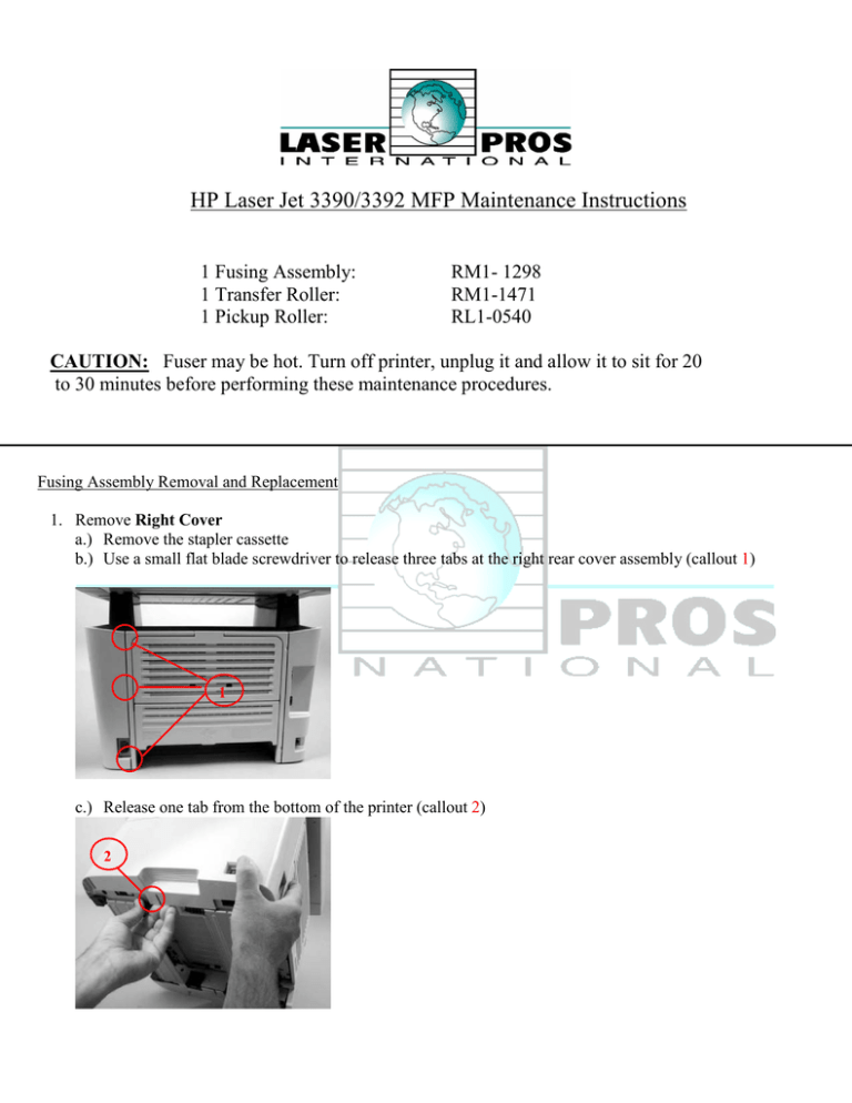
HP Laser Jet 3390/3392 MFP Maintenance Instructions 1 Fusing Assembly: 1 Transfer Roller: 1 Pickup Roller: RM1- 1298 RM1-1471 RL1-0540 CAUTION: Fuser may be hot. Turn off printer, unplug it and allow it to sit for 20 to 30 minutes before performing these maintenance procedures. Fusing Assembly Removal and Replacement 1. Remove Right Cover a.) Remove the stapler cassette b.) Use a small flat blade screwdriver to release three tabs at the right rear cover assembly (callout 1) 1 c.) Release one tab from the bottom of the printer (callout 2) 2 d.) Rotate the back of the cover away form the printer, then slide the cover forward to remove right cover 2. Remove Left Cover a.) Open toner cartridge door, use a small flat blade screwdriver to release one tab at the upper front of left cover (Callout 3) 3 b.) Release one tab from the bottom of left cover (callout 4) 4 c.) Rotate the front of the left cover away the printer, then slide the left cover backwards to remove 3. Remove rear cover a.) Remove four screws (callout 5) 5 b.) Use a small flat blade screwdriver to release the duplex-pan assembly hinge (callout 6) at the power plug side of the assembly and separate the rear cover from the printer to remove it 6 c.) Hint; When reinstalling rear cover, make sure the sensor flag is through the opening in rear cover 4. Remove Scanner/ADF assembly a.) Disconnect two flat ribbon cable (callout 7; J1 & J4), and two wire harness connectors (callout 8; J2 & P2) from formatter. Disconnect one ground wire lug (callout 9) from all-in-one chassis. 7 8 9 b.) Remove four screws (callout 10) 10 c.) Slide scanner/ADF assembly toward the front of the printer, and the lift up to remove it d.) WARNING! The scanner cover (which contains the ADF assembly) is not captive when the scanner assembly is removed. The scanner cover can suddenly open and be damaged when you are handling the scanner assembly. You must keep the scanner assembly level to make sure that the scanner cover (ADF assembly) does not open. CAUTION Make sure that you carefully pass the scanner wire-harnesses through the opening in the top cover. The connectors can be damaged if they become caught on the top cover. 5. Remove Top Cover a.) Open toner cartridge door and loosen, but do NOT remove, two screws (callout 11) 11 b.) Remove two screws from back of printer (callout 12) 12 d.) Remover four screws (callout 13), and the lift up on top cover to remove it 13 6. Remove Stapler Assembly (HP Laser Jet 3392 MFP only) a.) Disconnect one cable connector (callout 14) 14 b.) Remove two screws (callout 15), separate the stapler assembly from the printer chassis to remove it 15 7. Removing Stapler Power Supply (HP Laser Jet 3392 MFP only) a.) Remove one screw (callout 16), and then remove metal strap 16 b.) Disconnect one connector and remove stapler power supply 8. Removing Power-switch PCA a.) Disconnect two cable connectors (callout 17) and two screws (callout 18) NOTE: HP Laser Jet 3392 has one additional connector to disconnect (callout 19) b.) Separate the power-switch PCA (callout 20) from the printer 17 19 20 18 9. Remove Formatter a.) Disconnect three wire connecters (callout 21; P13,P14,P15) and three ribbon cables (callout 22; J7,J10,J11) 22 21 b.) Remove three screws form metal cover (callout 23) then remove metal cover 23 c.) Remove four screws from formatter (callout 24), Then remove formatter from printer 24 10. Remove Fan a.) Disconnect one connector (callout 25) from the ECU and feed the wire harness through the hole in the chassis (the hole is behind the power switch PCA. It is easier to feed the wire with the power switch PCA removed but not necessary) 25 b.) Remove two screws (callout 26) then lift the fan off the printer 26 11. Remove three screws (callout 27) and the carefully lift duplex drive assembly away the printer. (NOTE: THE GEARS ON THE DUPLEX DRIVE ASSEMBLY ARE NOT ATTACHED TO THE PLATE. CAREFULLY REMOVE GEARS AND GEAR PLATE TOGETHER TO PREVENT THEM FROM SEPERATING.) 27 12. Remove Duplex Solenoid a.) Disconnect one cable connector (callout 28, J211) from the ECU. Feed the wire harness out of the wire harness guides on the printer 28 b.) Remove one screw (callout 29) and the remove solenoid. The solenoid lever (callout 30) is not retained. Do not lose this lever! 29 30 13. Removal of fuser a.) On the right of printer, press the two tabs on the two gears (callout 31) to release and remove gears. 31 b.) Disconnect four connectors (callout 32) from the ECU. Remove the wire harness for the guises (callout 33). 32 33 c.) Pull the tabs on the wire harness holders (callout 34), then slide wire harness holders towards the center on printer and remove. 34 d.) Disconnect three wire connectors (callout 35). 35 e.) Pull wire harness holder (callout 36) straight back to remove it, then remove the wire harness from guide. 36 f.) Remove one screw (callout 37) and release one clip (callout 38) on the wire guide for optional tray three. It is not necessary to remove the tray three connector or wire harness guide. You do need to release the guide so that the tray three connector wire harness is loose enough to be removed from guide on the fuser later in this procedure. 38 37 g.) Disconnect one connector (callout 39) and then remove the wire harness from the guide. Before you proceed to the next step, make sure that all of the wire harnesses that you disconnected in previous steps have been released from any wire harness guides and holders. 39 h.) Remove three screws (callout 40) from the right rear of printer. 40 i.) Remove three screws (callout 41) from the left rear of printer. 41 j.) From the back, pull on the upper right side of printer to spread chassis to release fuser form the frame. k.) Pull the fuser out of the printer at an angle so that the delivery roller shaft clears the hole (callout 42) in the chassis. Carefully remove the wire harness from the guide in the lower left corner of the fuser. 42 l.) To reinstall fuser reverse all steps. Transfer Roller Removal and Replacement 1. 2. 3. 4. Open toner access door Remove toner cartridge Locate the bushing on right side next to the drive gear Squeeze the tabs on the bushing and lift up, slide to the right and remove 5. Tray 2 Pickup Roller Removal and Replacement 1. Removal of tray two pickup roller a.) Remove tray two b.) Tilt the front of the printer upward and press down of the green tab to release the duplex pan (callout 1) 1 c.) Pull the tab out and then rotate tab forward to release white retaining collar and remove left collar d.) Follow step c.) for right retaining collar but DO NOT REMOVE. Slide the pickup roller to the left to release right side of the pickup roller and remove. e.) Remove two screws on the separation pad assembly. Lift the separation pad assembly straight up to remove. Replace pad
