Bulletin No. 30072-005-101
November, 1991
Raleigh, NC, U.S.A.
Instruction Bulletin
Definite Purpose Contactor
Class 8910 Type DPA – 120 Amp
INTRODUCTION
This instruction bulletin illustrates and describes the Class 8910 definite purpose contactor.
It also contains assembly, operation, inspection, replacement and protection instructions.
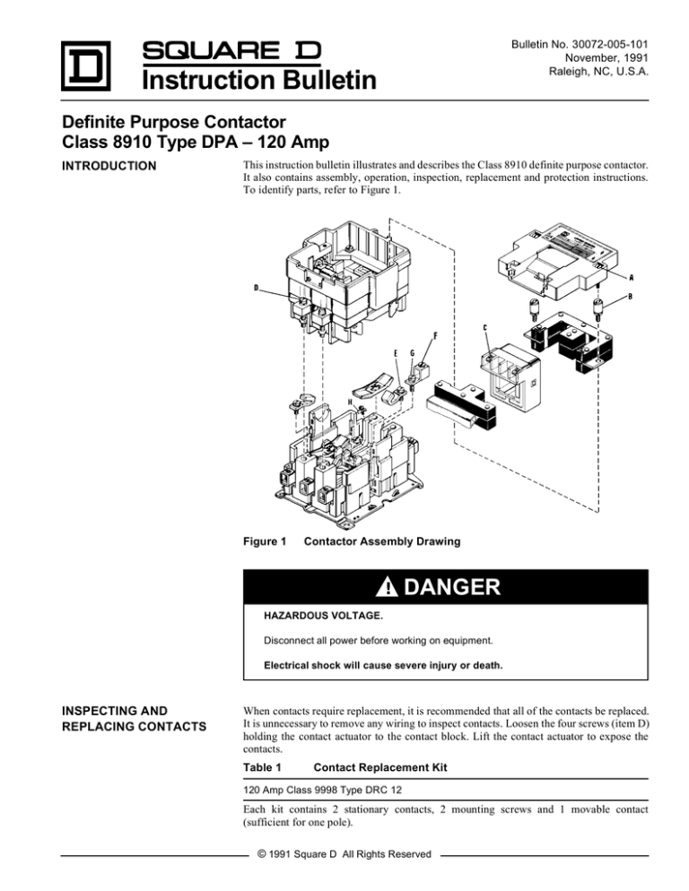
To identify parts, refer to Figure 1.
Figure 1
Contactor Assembly Drawing
!
DANGER
HAZARDOUS VOLTAGE.
Disconnect all power before working on equipment.
Electrical shock will cause severe injury or death.
INSPECTING AND
REPLACING CONTACTS
When contacts require replacement, it is recommended that all of the contacts be replaced.
It is unnecessary to remove any wiring to inspect contacts. Loosen the four screws (item D)
holding the contact actuator to the contact block. Lift the contact actuator to expose the
contacts.
Table 1
Contact Replacement Kit
120 Amp Class 9998 Type DRC 12
Each kit contains 2 stationary contacts, 2 mounting screws and 1 movable contact
(sufficient for one pole).
© 1991 Square D All Rights Reserved
Bulletin No. 30072-005-101
November, 1991
MANUAL OPERATION
!
WARNING
HAZARDOUS VOLTAGE.
Disconnect all power before manually operating equipment.
Manual operation with power on can cause contact arcing and unexpected
energization of load, resulting in personal injury or equipment damage.
Manual operation of contactors may be accomplished by pushing the contact carrier down
with a screwdriver. There is a step on the outside of the contact carrier that is suitable for
this use.
COIL REPLACEMENT
To remove the coil, loosen the two captive cover screws (item A). Disconnect wires from
the coil terminals and remove the cover. Loosen the two screws (item B) holding the magnet
in place. Remove the coil and magnet assembly. Separate the coil from the magnet assembly.
To replace the coil, first assemble the magnet, coil and armature and insert as a unit.
Approximately 3/8" of space should exist between the top outside surface of the coil and
the inside surface of the magnet. If this space does not exist and the magnet is loose and not
quite in place, grasp the coil firmly and slide it down toward the armature. The magnet will
then fall in place.
Before installing the cover, manually operate the device as described in “Manual
Operation” to insure that all parts are functioning properly. Follow the recommended
tightening torques listed in Table 2 when reassembling the device.
Table 2
Item
Factory Recommended Tightening Torques
Description
Tightening
Torque (in-lb)
A ........ Cover screws ........................................................ 24-28
B ........ Screw post ............................................................ 65-75
C........ Coil terminal pressure wire connector .................. 9-12
D........ Power plant screw ................................................ 40-45
E ........ Stationary contact fasteners ................................. 44-50
F ........ Wire retaining screw ............................................. 100
G........ Lug retaining screw............................................... 44-50
H........ Control circuit pressure wire connector ................ 9-12
SHORT CIRCUIT
PROTECTION
Suitable for use on a circuit capable of delivering not more than 10,000 rms symmetrical
amperes, 600 volts maximum. Rating of branch-circuit protective device must comply with
applicable electrical codes and the maximum protective device ratings listed in Table 3.
Table 3
Maximum Ampere Rating
Type of Device
Class K5 or RK5 fuse (time delay may be required)
Class J, RK1 or T fuse1
Inverse-time circuit breaker
1Class
PLEASE NOTE:
Page 2
Maximum Rating
175 A
350 A
175 A
T fuse is 250 volts maximum.
Electrical equipment should be serviced only by qualified electrical maintenance personnel, and this
document should not be viewed as sufficient instruction for those who are not otherwise qualified to
operate, service or maintain the equipment discussed. Although reasonable care has been taken to provide
accurate and authoritative information in this document, no responsibility is assumed by Square D for
any consequences arising out of the use of this material.
© 1991 Square D All Rights Reserved

