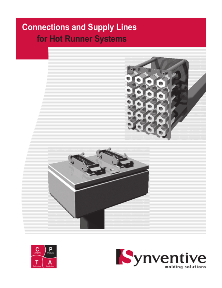
Connections and supply lines for hot runner systems
Connections and Supply
Lines
for Hot Runner Systems
C P
T A
Illustrations simplified, schematically drawn and not to scale.
C
Company
P
Products
2006-08-19 - All rights reserved. Errors and omissions excepted.
For a specific application, please consult Synventive.
T
Technology
A
Application
For design and application information,
see the Synventive Hot Runner Guide.
Connections and supply lines for hot runner systems
Overview
C P
T A
Illustrations simplified, schematically drawn and not to scale.
Product type
Connections and supply lines for hot runner
systems with the following functions and
installation types:
1
.
2..
1. Wiring
Power
è
Signals
è
2. Piping
è
Compressed air supply
è
Hydraulic oil supply
è
Cooling water supply
2
4
3. Installation inside mould
All wires and hoses are installed in grooves
and cut outs inside the mould.
Power and signals
a) Heaters and thermocouples of the nozzles
b) Heaters and thermocouples of the manifold
and the inlet bushing
3
4
Hoses
c) Cooling water supply to cool the actuators
d) Pressure supply to the actuators
a)
4. Installation inside wire and hose guards
All wires and hoses are installed inside guards
which are attached to the hot runner system.
e) Wire guard with retainer plate for the
connection box
f) Hose guard with connection plate for the
hoses
5. Application example
e)
b)
f)
a)
c)
d)
5
8
page no. of related data sheets
2006-08-19 - All rights reserved. Errors and omissions excepted.
For a specific application, please consult Synventive.
1/4
For design and application information,
see the Synventive Hot Runner Guide.
Connections and supply lines for hot runner systems
Wiring: Connectors, pin assignment, heater zone numbering
C P
T A
Illustrations simplified, schematically drawn and not to scale.
When hot runner systems are wired the
selection of the connectors as well as the pin
assigment and the heater zone numbering
are done according to customer specification.
1
a)
b)
1. Connectors
Shown on the right there are examples for
connector inserts and housing as they are
used for hot runner systems.
a) Pin insert
b) Socket insert
For power supply e g at the temperature
controller socket inserts have to be used in
order to avoid danger of electric shock as it is
the case when pin inserts are used.
2. Standard pin assignment
If no customer specification is available the
pin assigment can be done accoridng to
Synventive standard as shown for a 24 pin
connector on the right.
1, 2, 3
Number of heater zones
230 V AC Heater zone power supply
TC
Signal line to the thermocouples,
several colour codings shown below
1) Standard
230 V AC
1, 2, 3 ... 6
2
TC
1, 2, 3 ... 6
a)
3. Numbering of heater zones
If no customer specification is available the
heater zones can be numbered accoridng to
Synventive standard:
Heater zone numbering is done opposite to
è
melt flow direction.
Heater zones of similar components are
è
numbered together.
This means concretely:
1). Nozzles
è
from tip to nozzle head
è
in the same order as nozzle numbering
1
2). Manifold
è
starting at nozzle no. 1
è
in the same order as nozzle numbering
3
2
3
TC
3). Inlet bushing
è
starting at the manifold
è
to direction of machine nozzle
1
230 V AC
Typ
DIN 43722
black
Fe / CuNi J
1)
green
black
blue
red
L
white
green
NiCr / Ni K
green
2/4
3
1
blue
red
black
white
yellow
3
NF C 42 - 324
black
yellow
J
red
yellow magenta
K
green
2
ANSI MC 96.1
J
K
white
2006-08-19 - All rights reserved. Errors and omissions excepted.
For a specific application, please consult Synventive.
DIN 43714
2
black
yellow
J
black
yellow
K
red
BS4937 / 1843
red
blue
brown
K
magenta
blue
For design and application information,
see the Synventive Hot Runner Guide.
Connections and supply lines for hot runner systems
Wiring: Connection box
C P
T A
Illustrations simplified, schematically drawn and not to scale.
When hot runner systems are wired the
selection of the connection box and the
design of the wire guards are done according
to customer specification.
1
1. Connection box
Shown on the right there are two examples
for conection boxes as they are used for hot
runner systems.
2. Wire guard
Shown on the right there are the basic
components of wire guards which are
mounted to the hot runner system.
a) Retainer plate for connection box
b) Wire guard
w 41 mm
h 41 / 62 / 83 mm
2
a)
h
w
b)
2006-08-19 - All rights reserved. Errors and omissions excepted.
For a specific application, please consult Synventive.
3/4
For design and application information,
see the Synventive Hot Runner Guide.
Connections and supply lines for hot runner systems
Piping: Connection plate and hose guard
C P
T A
Illustrations simplified, schematically drawn and not to scale.
When hot runner systems are piped the
installation of hoses and the design of the
hose guard are done according to customer
specification.
1
Shown on the right there are the basic hose
guard components which are mounted to the
hot runner system.
3
1. Connection plate
The plate with room for 6 fittings as shown on
the right is the basic element for all connection plates. The assignment of the connections is done according to customer
specification.
2
a) Example: Connections for a 2-port valve
gate system
1
2. XAP ...
Fitting
Tp1
(mm)
Tp2
(mm)
XAP 014 014
M14
M14
XAP 014 104
M14
G1/4
XAP 014 106
M14
G3/8
XAP 014 108
M14
G1/2
XAP 016 016
M16
M16
XAP 016 104
M16
G1/4
XAP 016 106
M16
G3/8
XAP 016 108
M16
G1/2
a)
open
close
open
close
in
out
cylinder 1
cylinder 2
cooling
cylinder 1 & 2
40 x 40 mm
60 x 40 mm
60 x 60 mm
60 x 80 mm
60 x 100 mm
60 x 120 mm
80 x 80 mm
80 x 100 mm
80 x 120 mm
Tp2
wxh
Tp1
3. Hose guard
b) Retainer plate for the connection plate
c) Hose guard
2
3
b)
w
h
c)
2006-08-19 - All rights reserved. Errors and omissions excepted.
For a specific application, please consult Synventive.
4/4
For design and application information,
see the Synventive Hot Runner Guide.
Connections and supply lines for hot runner systems
C P
www.synventive.com
T A
Illustrations simplified, schematically drawn and not to scale.
2006-08-19 - All rights reserved. Errors and omissions excepted.
For a specific application, please consult Synventive.
MK-PRM.BRM.GB-P.CONCTN 2009-05-01
For design and application information,
see the Synventive Hot Runner Guide.

