Position Transmitters and Limit Switches XFlo
advertisement
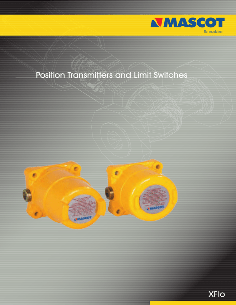
Position Transmitters and Limit Switches XFlo Position Transmitters (XFlo) Design: Features that spell Reliability Today's modern process control systems need Position Transmitters (XFlo) position transmitter and switches that deliver the level of accurate position sensing need. FEATURES AND ADVANTAGES: High accuracy Accurate transmission of linear signal within +_ 1.0 percent across the whole range.Two-wire design The unique two-wire design reduces field wiring costs. The infinite resolution potentio-meter in Position Transmitters (XFlo) senses the exact position of a valve coupled with a two-wire transmitter and sends a continuous 4-20mA signal to a remote indicating device. Easy field adjustments Convenience of easy field adjustments cover non interacting multi-turn zero and span settings, reverse polarity action switch, clockwise or counter clockwise operation. The Position Transmitters (XFlo) output can be comfortably adjusted from 5 to 90 degree input rotation with multi-turn zero and span adjustments. The reversing of action is accomplished easily by a switch located on the circuit board. Position Transmitters (XFlo) can be ordered with the analog 4-20mA position transmitter either alone or with two independently adjustable (SPDT) limit switches. Also available are models with two (LS2) or four (LS4) independently adjustable limit switches only. Rugged cast aluminum housing Cast aluminum housing that it is explosion proof, weather proof and dust proof Shock and vibration resistant Highly resistant to shocks and vibrations and withstands acceleration forces to 483 ft/sec2. Independent operation There is an independent operation between limit switches and transmitter. Another important feature of the Position Transmitters (XFlo) rugged cast aluminum housing is that it is explosion proof, weather proof and dust proof. Humidity protection is provided to the transmitter circuit with conformal coating. The transmitter circuit incorporates solid state integrated circuitry with few components for reliable performance. Multiple usages Installation of multiple usage on linear and rotary actuators, louvers, dampers and other devices. Stable operation Highly stable while operating in ambient temperature changes and fluctuations of power supply. Adjustable span from 5 degree to 90 degree rotation of shaft. For standard Mascot linear and rotary actuators, mounting hardware is available. Another utility for Position Reverse polarity protected Trouble free installation because of reverse polarity protection. Meets with IS 2148-1981 for group II A, IIB & II C. Rugged Cast aluminium Casting Diverse Mounting Capability Optional independent limit switches Explosion and whether proof Temperature Compansated Circuitry Infinite resistance potentio meter Field reversible Signal Non-interacting Zero and Span setting Built in two-wire Transmitter with 4-20mA output Reverse polarity protected 2 Position Transmitters (XFlo) Specification Table I: Specifications Analog Output 12.5 to 40 VDC (24V DC typical) Maximum load resistance (see figure 3) Maximum Resistance (ohms) = Supply Voltage - 12.5 .02 4-20 mA Current signal output span ccw cw zero + Power supply range Ð R L2 LOAD D.C. + Power Supply Span Adjustable from 5 ° to 100 ° of angular rotation Null 4 mA position may be set at any angular position Linearity Repeatability ±1.0% full scale* ±0.25% full scale Hysteresis ±1.0% full scale Operating temperature range -40 O to 185 O F (-40 O to 85 O C) Ambient temperature range For a 100 O F (38 O C) change in ambient temperature, maximum zero shift is ±0.4% full scale, maximum span shift is ±0.7% full scale Power Supply Output signal changes less than 0.05% when supply voltage is varied between 12.5 and 40 volts dc R L1 Limit Switches (SPDT) UL/CSA Rating (L23) Mechanical 1500 Input motion 1250 Maximum Load Resistance, RL (Ω) 20 amps, 125, 250, 480 VAC, ind. and res. 1 Hp. 125 VAC; 2 Hp, 250 VAC, .5 amp. 125 VDC; .25 amp, 250 VDC res. * Linearity is ±1.0% for 90 O rotary shaft input. When mounted to linear travel valves, linearity is dependent on linkage design and stroke length. Typical linearity is ±1.5% full scale on G Series valves. R L max= V PS- 12.5V 20 mA 1000 ±105 O from the center; spring loaded to return to the center 750 Table II: Model Configuration Description 500 0 0 10 20 30 40 Housing Size Short PTLS2 Long LS2 LS4 Short Long Two SPDT switches with terminal switch P2TS Long Two SPDT switches with terminal strip P2TSt Long Analog transmitter only Analog transmitter with two SPDT switches Operating Region 250 Model Number PT 50 60 Two SPDT switches only Four SPDT switches only Power Supply Voltage, V PS(volts) Figure 3: Power Supply Requirements 3 Position Transmitters (XFlo) Dimension Mounting Dimensions (inches / mm) Rotary Short Housing 1.26 dia. max. 32 .72 18 4.00 102 1.57 40 3.15 80 Long Housing .88 22 4.09 max. 104 .88 22 5.71 max. 145 .37 9 3.78 max. 96 .37 9 3.78 max. 133 3.86 dia. 98 2.38 typ 60 2.00 51 3/4 - 14 NPT (5 full threads min.) (2) .80 20 .33 dia. thru (4) 8 1.00 25 3.82 dia. 97 .29 dia. 7 .80 20 Eight side mounting holes can be tapped 5/16 - 18-inch 3/4 - 14 NPT (5 full threads min.) (2) 1.00 25 .50 13 .49 12 1.00 25 Lever Actuators .75 19 Adjust 1.50 - 3.70 38 - 94 .25 6 1.50 38 Front Mounting .83 21 .57 14 4.04 103 .27 7 .39 10 .72 18 .74 19 .16 4 .16 4 .31 8 .09 2 Best efforts have been made to keep the information accurate. The literature is for information and should not be considered as certified or as a guarantee of results by relying on it. No part of this literature is to be construed as a warranty or guarantee, expressed or implied, regarding any matter with respect to the product. Continual up-gradation in product design being imperative, the dimensions, specifications, design and information are subject to change without notice. Please consult our representative or factory for details. Instructions for installation, operation, maintenance or trouble shooting of Position Transmitters (XFlo) are contained in the Installation, Operation and Maintenance instructions section. These instructions should be read and understood thoroughly and followed in exactness by all personnel responsible for these operations. Installation, Operation, Maintenance instructions are provided by us through our representatives on field or at our factory and office. 166 / 167, G I D C, Naroda, Ahmedabad : 382330. India Phone : +91 79 22821619/22823369, Fax : +91 79 22822430 Email : info@mascotvalves.com / web : www.mascotvalves.com
