9A483001 Installation Instructions
advertisement

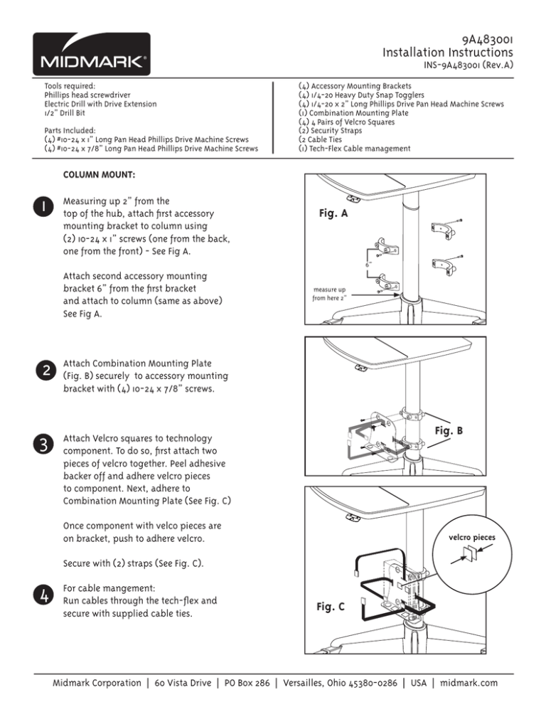
9A483001 Installation Instructions INS-9A483001 (Rev.A) Tools required: Phillips head screwdriver Electric Drill with Drive Extension 1/2” Drill Bit Parts Included: (4) #10-24 x 1” Long Pan Head Phillips Drive Machine Screws (4) #10-24 x 7/8” Long Pan Head Phillips Drive Machine Screws (4) Accessory Mounting Brackets (4) 1/4-20 Heavy Duty Snap Togglers (4) 1/4-20 x 2” Long Phillips Drive Pan Head Machine Screws (1) Combination Mounting Plate (4) 4 Pairs of Velcro Squares (2) Security Straps (2 Cable Ties (1) Tech-Flex Cable management COLUMN MOUNT: 1 Measuring up 2” from the top of the hub, attach first accessory mounting bracket to column using (2) 10-24 x 1” screws (one from the back, one from the front) - See Fig A. Fig. A 6” Attach second accessory mounting bracket 6” from the first bracket and attach to column (same as above) See Fig A. 2 Attach Combination Mounting Plate (Fig. B) securely to accessory mounting bracket with (4) 10-24 x 7/8” screws. 3 Attach Velcro squares to technology component. To do so, first attach two pieces of velcro together. Peel adhesive backer off and adhere velcro pieces to component. Next, adhere to Combination Mounting Plate (See Fig. C) measure up from here 2” Fig. B Once component with velco pieces are on bracket, push to adhere velcro. velcro pieces Secure with (2) straps (See Fig. C). 4 For cable mangement: Run cables through the tech-flex and secure with supplied cable ties. Fig. C Midmark Corporation | 60 Vista Drive | PO Box 286 | Versailles, Ohio 45380-0286 | USA | midmark.com 9A483001 Installation Instructions INS-9A483001 (Rev.A) Tools required: Phillips head screwdriver Electric Drill with Drive Extension 1/2” Drill Bit Parts Included: (4) #10-24 x 1” Long Pan Head Phillips Drive Machine Screws (4) #10-24 x 7/8” Long Pan Head Phillips Drive Machine Screws 2 FOR WALL-MOUNT: 1 (4) Accessory Mounting Brackets (4) 1/4-20 Heavy Duty Snap Togglers (4) 1/4-20 x 2” Long Phillips Drive Pan Head Machine Screws (1) Combination Mounting Plate (4) 4 Pairs of Velcro Squares (2) Security Straps (2 Cable Ties (1) Tech-Flex Cable management Caution Once togglers are installed, attach CPU Mounting Bracket with (4) 1/4-20 x 2” Long Phillips Drive Pan Head Machine Screws Properinstallationoftoggleboltsrequired toprovidesecurewallmounting.Minimum drywallthicknesstobe½”. Prior to installing CPU bracket assembly to wall, follow instructions to install heavy duty snap togglers into wall. 1. (1/2” Hole) Drill 1/2” size hole. Hold metal channel flat alongside plastic straps and slide channel through the hole. Minimum clearance beind wall: only 1 7/8” Attach component to CPU mounting Bracket by securing with Security Straps. 2. 3. Midmark Corporation | 60 Vista Drive | PO Box 286 | Versailles, Ohio 45380-0286 | USA | midmark.com


