Document
advertisement

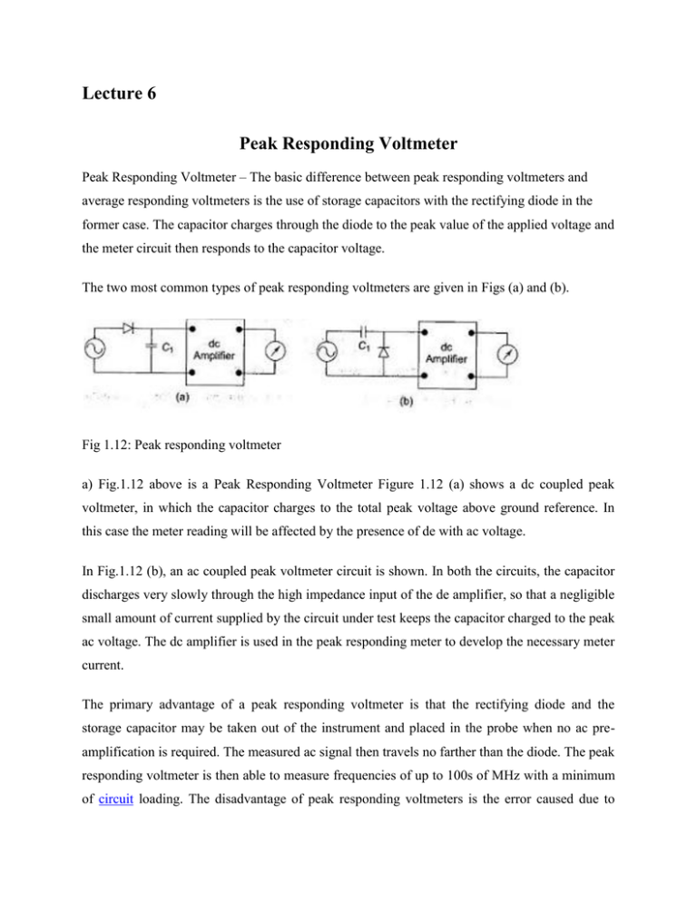
Lecture 6 Peak Responding Voltmeter Peak Responding Voltmeter – The basic difference between peak responding voltmeters and average responding voltmeters is the use of storage capacitors with the rectifying diode in the former case. The capacitor charges through the diode to the peak value of the applied voltage and the meter circuit then responds to the capacitor voltage. The two most common types of peak responding voltmeters are given in Figs (a) and (b). Fig 1.12: Peak responding voltmeter a) Fig.1.12 above is a Peak Responding Voltmeter Figure 1.12 (a) shows a dc coupled peak voltmeter, in which the capacitor charges to the total peak voltage above ground reference. In this case the meter reading will be affected by the presence of de with ac voltage. In Fig.1.12 (b), an ac coupled peak voltmeter circuit is shown. In both the circuits, the capacitor discharges very slowly through the high impedance input of the de amplifier, so that a negligible small amount of current supplied by the circuit under test keeps the capacitor charged to the peak ac voltage. The dc amplifier is used in the peak responding meter to develop the necessary meter current. The primary advantage of a peak responding voltmeter is that the rectifying diode and the storage capacitor may be taken out of the instrument and placed in the probe when no ac preamplification is required. The measured ac signal then travels no farther than the diode. The peak responding voltmeter is then able to measure frequencies of up to 100s of MHz with a minimum of circuit loading. The disadvantage of peak responding voltmeters is the error caused due to harmonic distortion in the input waveforms and limited sensitivity of the instrument because of imperfect diode characteristics. True RMS Voltmeter: True RMS Voltmeter – Complex waveform are most accurately measured with an rms voltmeter. This instrument produces a meter indication by sensing waveform heating power, which is proportional to the square of the rms value of the voltage. This heating power can be measured by amplifying and feeding it to a thermocouple, whose output voltages is then proportional to the Erms. However, thermocouples are non-linear devices. This difficulty can be overcome in some instruments by placing two thermocouples in the same thermal environment. The effect of non-linear behaviour of the thermocouple in the input circuit (measuring thermocouple) is cancelled by similar non-linear effects of the thermocouple in the feedback circuit (balancing thermocouple). The two couples form part of a bridge in the input circuit of a dc amplifier. Fig 1.13: True RMS voltmeter The unknown ac voltage is amplified and applied to the heating element of the measuring thermocouple. The application of heat produces an output voltage that upsets the balance of the bridge. The dc amplifier amplifies the unbalanced voltage; this voltage is fed back to the heating element of the balancing thermocouple, which heats the thermocouple, so that the bridge is balanced again, i.e. the outputs of both the thermocouples are the same. At this instant, the ac current in the input thermo-couple is equal to the dc current in the heating element of the feedback thermocouple. This dc current is therefore directly proportional to the effective or rms value of the input voltage, and is indicated by the meter in the output circuit of the dc amplifier. If the peak amplitude of the ac signal does not exceed the dynamic range of the ac amplifier, the true rms value of the ac signal can be measured independently.


