Turbulence and Detonation Limits
advertisement

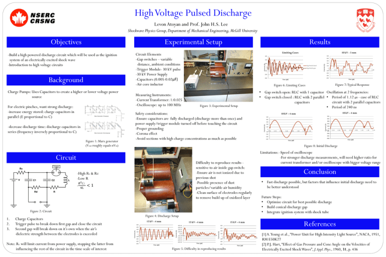
High Voltage Pulsed Discharge Levon Atoyan and Prof. John H.S. Lee Shockwave Physics Group, Department of Mechanical Engineering, McGill University Experimental Setup Background Charge Pumps: Uses Capacitors to create a higher or lower voltage power source Figure 1: Marx generator (Vout roughly equals nVin) 1.90 3.90 5.90 Gap Switch open 7.90 Current (A) Current (A) Gap Switch closed 200 100 0 -1000.00 0.50 1.50 2.00 2.50 3.00 3.50 4.00 -300 -300 -400 Time (μs) Time (μs) Figure 7: Typical Response Figure 6: Limiting Cases Measuring Instruments: -Current Transformer: 1:0.025 -Oscilloscope: up to 100 MHz 1.00 -200 -200 • Gap switch open: RLC with 1 capacitor Oscillation at 2 frequencies: • Gap switch closed : RLC with 2 parallel • Period of 1.12 µs - case of RLC circuit with 2 parallel capacitors capacitors • Period of 240 ns Figure 3: Experimental Setup Safety considerations: -Ensure capacitors are fully discharged (discharge more than once) and power supply/trigger module turned off before touching the circuit -Proper grounding -Corona effect -Avoid sections with high charge concentrations as much as possible 10 kV - 4 mm 10 kV - 4 mm 500 500 400 400 300 300 200 100 0 -1000.00 0.20 0.40 0.60 0.80 1.20 1.40 100 0 -0.10 -100 0.10 0.30 0.50 0.70 0.90 1.10 1.30 1.50 -300 -300 -400 1.00 200 -200 -200 -400 Time (μs) Time (μs) Figure 8: Initial Discharge Limitations: -Speed of oscilloscope -For stronger discharge measurements, will need higher ratio for current transformer and/or oscilloscope with bigger voltage range Difficulty to reproduce results sensitive to air inside gap switch: -Ensure air is not ionized due to previous shot -Possible presence of dust particles/variable air humidity -Clean surface of electrodes regularly to remove build up of oxidized layer Conclusion • Fast discharge possible, but factors that influence initial discharge need to be better understood Future Steps: • Optimize circuit for best possible discharge • Build conical discharge gap • Integrate ignition system with shock tube Figure 2: Circuit Figure 4: Discharge Setup 15 kV - 4 mm 15 kV - 4 mm Current (A) 400 200 0 -2000.00 1.00 2.00 3.00 -600 -800 Time (μs) 4.00 5.00 6.00 Current (A) 600 800.00 600.00 400.00 200.00 0.00 -200.000.00 -400.00 -600.00 -800.00 References 15 kV - 4 mm 800 600 1.00 2.00 3.00 4.00 Current (A) 800 -400 Note: Rc will limit current from power supply, stopping the latter from influencing the rest of the circuit in the time scale of interest 300 0 -0.10 -100 <1 Charge Capacitors Trigger pulse to break down first gap and close the circuit Second gap will break down on it’s own when the air’s dielectric strength between the electrodes is exceeded 400 100 -High Rc & Rd -Low R 1. 2. 3. 500 200 Circuit 𝑅 2 C2 4𝐿 10 kV - 3 mm 300 Current (A) -decrease discharge time: discharge capacitors in series (frequency inversely proportional to C) Limiting Cases Circuit Elements -Gap switches – variable distance, ambient conditions -Trigger Module- 30 kV pulse -30 kV Power Supply -Capacitors (0.005-0.02μF) -Air core inductor -Build a high powered discharge circuit which will be used as the ignition system of an electrically excited shock wave -Introduction to high voltage circuits For electric pinches, want strong discharge: -increase energy stored: charge capacitors in parallel (E proportional to C) Results Current (A) Objectives 400 200 0 -200 0.00 1.00 2.00 -400 Time (μs) -600 Figure 5: Difficulty in reproducing results Time (μs) 3.00 4.00 [1] A.Young et al., “Power Unit for High Intensity Light Source”, NACA, 1951, RM E50K27 [2] P.J. Hart, “Effect of Gas Pressure and Cone Angle on the Velocities of Electrically Excited Shock Waves”, J. Appl. Phys., 1960, 31, p. 436


