Document No. 10860038 Rev. D
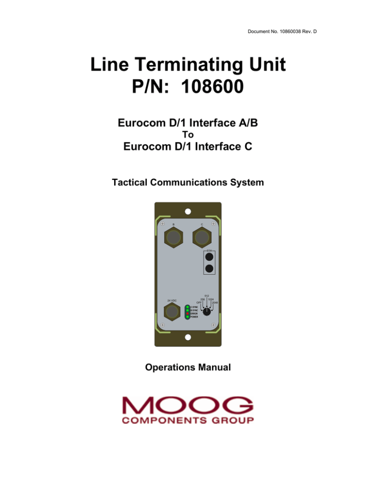
Line Terminating Unit
P/N: 108600
Eurocom D/1 Interface A/B
To
Eurocom D/1 Interface C
Tactical Communications System
B
C
EOW
24 VDC
512
256 1024
OFF
2048
C SYNC
B SYNC
ERROR
POWER
Operations Manual
Line Terminating Unit
P/N: 108600
Eurocom D/1 Interface A/B
To
Eurocom D/1 Interface C
Tactical Communications System
Operations Manual
Moog Components Group
www.moog.com/components
750 West Sproul Road
Springfield, PA 19064-4084
(610) 328-4000
Doc. No. 10860038, January 20, 2006, Rev. D
Copyright (c) 2006 Moog Components Group
All Rights Reserved.
Any unauthorized duplication or use, in whole or in part, in print or in any other
storage retrieval system is prohibited. No part of this material may be
reproduced, transmitted, transcribed, stored in a retrieval system, or translated
into any language in any form by any means for any purpose other than licensed
use without the express written permission of Moog Components Group.
REVISION HISTORY
Revision
Description
Date
Approval
A
Original Release
04/17/02
R. Stenzel
B
Revised to incorporate 05/11/02
improvements submitted
by users of this manual.
R. Stenzel
C
Revised Figures 1 & 8
to show new positions
of rear DATA IN / DATA OUT
binding posts.
08/26/02
R. Stenzel
D
Revised logo and
name from Northrop
Grumman Component
Technologies, PolyScientific, to Moog
Components Group.
01/20/06
R. Stenzel
LTU Operations Manual
Page i
Rev. D / January 20, 2006
Special Notice
The material contained in this manual is solely for the
information of customers and potential customers
of Moog Components Group, and in no way be
construed to constitute specifications, warranties, or
other contractual terms.
At the time of printing, the information contained in
this document was believed to be accurate to the
best of Moog Components Group knowledge. Moog
Components Group may not be held responsible for
inadvertent errors. Moog Components Group reserves
the right to change the contained information without prior
notice.
This data shall not be disclosed outside the addressee’s
organization and shall not be duplicated, used, or
disclosed, in whole or in part, for any other purpose than
to evaluate, operate, or maintain Moog Components
Group equipment. This restriction does not limit the
addressee’s right to use the information contained herein
if it is obtained from another source without restriction.
The data subject to this restriction is contained in all
pages of this document.
LTU Operations Manual
Page ii
Rev. D / January 20, 2006
Table of Contents
1.0 Introduction .............................................................. 1
1.1 General ...................................................................... 1
1.2 Abbreviations & Definitions ........................................ 2
2.0 Technical Data.......................................................... 3
2.1 Definition .................................................................... 3
2.2 Physical Dimensions .................................................. 3
2.3 Electrical Data ............................................................ 4
2.4 Electrical Interface...................................................... 5
3.0 Design & Functions ................................................. 8
3.1 General ...................................................................... 8
3.2 Mounting .................................................................... 9
3.3 Connections ............................................................... 9
4.0 Operation & Handling .............................................. 10
4.1 General ...................................................................... 10
4.2 Connection & Operation............................................. 10
4.3 Regenerator ............................................................... 11
4.4 Error Indicator ............................................................ 12
4.5 C-Sync Indicator......................................................... 12
4.6 B-Sync Indicator......................................................... 12
4.7 Power Indicator .......................................................... 12
5.0 Maintenance ............................................................. 13
5.1 General ...................................................................... 13
5.1 Cleaning..................................................................... 13
5.3 Inspection................................................................... 13
5.4 Troubleshooting ......................................................... 14
LTU Operations Manual
Page iii
Rev. D / January 20, 2006
List of Figures
Figure 1: 108600 Line Terminating Unit ......................... 1
Figure 2: B Interface Contact Arrangement .................... 5
Figure 3: C Interface Contact Arrangement.................... 6
Figure 4: Power Supply Contact Arrangement ............... 7
Figure 5: System Interconnect........................................ 8
Figure 6: Rack Mounted (19” Rack)................................ 9
Figure 7: Front Panel...................................................... 10
Figure 8: Connection of Field Cable at Rear .................. 11
Figure 9: Connection of Regenerators............................ 11
Figure 10: Main Troubleshooting Flowchart ..................... 14
Figure 11: Troubleshooting the Power Indicator............... 15
Figure 12: Troubleshooting the B-Sync Indicator ............. 15
Figure 13: Troubleshooting the C-Sync Indicator ............. 16
Figure 14: Troubleshooting the Error Indicator ................. 16
List of Tables
Table 1:
EUROCOM B Interface ................................... 5
Table 2:
EUROCOM C Interface ................................... 6
Table 3:
Power Supply Interface ................................... 7
LTU Operations Manual
Page iv
Rev. D / January 20, 2006
1.0
Introduction
1.1
General
The purpose of this manual is to give the user the
necessary knowledge for connection and operation of
the Line Terminating Unit, part number 108600.
Figure 1: 108600 Line Terminating Unit
LTU Operations Manual
Page 1
Rev. D / January 20, 2006
1.2
Abbreviations & Definitions
AMI
Alternate Mark Inversion, a special
line code used in TDM interface,
EUROCOM A or EUROCOM B.
BFOM
Fiber Optic Modem (FOM) which
provides
electrical
to
optical
conversion
of
EUROCOM
B
electronic communication and data
signals for transmission using
tactical fiber optic cable. For more
information, visit our website at:
www.moog.com/components
EUROCOM
European standard for signaling
between military communications
equipment.
EUROCOM A
Interface for TDM-signaling. Range
of approximately 50 meters on a
multi-pair cable.
EUROCOM B
Encrypted EUROCOM A signal.
EUROCOM C Interface for signaling with a range
of approximately 1000 meters.
HDB-3
High Density Bipolar 3, a special
line code used in the TDM interface,
EUROCOM, with field cable WD1/TT.
LTU
Line Terminating Unit
TDM
Time Division Multiplexing
LTU Operations Manual
Page 2
Rev. D / January 20, 2006
2.0
Technical Data
2.1
Definition
The Line Terminating Unit includes the following:
Part Number
Description
108600
Line Terminating Unit
107715
TDM Signal Cable
108607-01
Power Cable (24 VDC)
10860038
Operations Manual
The 108600 is a unit which converts digital signals
from the EUROCOM A/B interface to the EUROCOM
C interface for full duplex transmission via a maximum
of 1000 meters of new, dry WD-1/TT field cable.
The TDM bit-rate can be selected between 256, 512,
1024, or 2048 kilobits per second.
2.2
Physical Data
4 units fit side-by-side in a standard 19” rack.
Metric
English
Width:
110 mm
4.32 Inches
Height:
235 mm
9.25 Inches
Depth:
89 mm
3.50 Inches
Weight:
1.14 kg
2.5 Pounds
Page 3
Rev. D / January 20, 2006
LTU Operations Manual
2.3
Electrical Data
Time Delay:
<12 bits per second between the
A/B and C interfaces.
Synchronization: Corrects up to ±60 ppm deviation
related to bit-rate.
B-interface:
Balance inputs, AMI-code 256, 512,
1024, or 2048 kilobits per second.
Input line length is 50 meters
maximum.
C-interface
Maximum cable length is 1000
meters with new, dry cable.
Maximum bit-rate error is 1X10⁻⁶.
Connection to socket on front panel
or binding posts on the rear of the
unit.
Power supply:
24 VDC nominal, 12 to 36 VDC Max
(independent of polarity)
Power
consumption:
5 Watts Maximum
Operation temp: -40°C to +55°C
Storage temp:
-55°C to +70°C
EOW:
Connection for field telephone (LB).
LTU Operations Manual
Page 4
Rev. D / January 20, 2006
2.4
Electrical Interface
Table 1: EUROCOM B Interface
Pin
E
F
G
H
J
K
L
M
V
A, B, C, D, N, P,
R, S, T, & U
B
C
D
A
P
R
E
F
V
M
L
U
T
G
No Connection
M
N
S
Function
Data Tx (a)
Data Tx (b)
Data Rx (a)
Data Rx (b)
Clock Tx (a)
Clock Tx (b)
Clock Rx (a)
Clock Rx (b)
Shield
L
K
K
J
N
U
J
H
B
P
V
T
H
LTU CONNECTOR:
AMPHENOL 71-533724-19S
A
C
R
S
G
D
E
F
MATING CONNECTOR:
MS3126F14-19P
Figure 2: B Interface Contact Arrangement
LTU Operations Manual
Page 5
Rev. D / January 20, 2006
2.4
Electrical Interface (continued)
Table 2: EUROCOM C Interface
Pin
A
B
C
D
E, F, G, H, J, K,
L, M, N, P, R, S,
T, U, & V
B
C
D
A
P
R
E
F
V
M
L
U
T
G
No Connection
M
N
S
Function
Data Tx
Data Tx
Data Rx
Data Rx
L
K
K
J
N
U
J
H
B
P
V
T
H
LTU CONNECTOR:
AMPHENOL 71-533724-19S
A
C
R
S
G
D
E
F
MATING CONNECTOR:
MS3126F14-19P
Figure 3: C Interface Contact Arrangement
LTU Operations Manual
Page 6
Rev. D / January 20, 2006
2.4
Electrical Interface (continued)
Table 3: Power Supply Interface (24VDC)
Pin
Function
A
DC Input (polarity independent)
B
Case Ground
C
DC Input (polarity independent)
C
A
A
C
B
B
LTU CONNECTOR:
AMPHENOL 71-533723-03P
MATING CONNECTOR:
MS3126F14-19S
Figure 4: Power Supply Contact Arrangement
LTU Operations Manual
Page 7
Rev. D / January 20, 2006
3.0
Design & Functions
3.1
General
The 108600 is a rugged, light weight transmission unit
for Eurocom networks, which converts digital signals
from EUROCOM A/B to EUROCOM C and visa
versa. It is used when the distance between relevant
equipment units is too long for EUROCOM A/B
transmissions, or when standard cable lengths are too
short. It is also used when equipment units with
different interface types are to be connected.
Note!
If EUROCOM A is connected directly to the
108600, this will operate as EUROCOM B,
but without encryption.
Engineering
Order Wire
B
Telephones
PTT / PBX
Terminals
Switches
Engineering
Order Wire
C
B
C
EOW
EOW
BFOM,
Radio,
or
Radio Relay
MUX
or
Switch
24 VDC
512
256 1024
OFF
2048
24 VDC
C SYNC
B SYNC
ERROR
POWER
EUROCOM A/B
512
256 1024
OFF
2048
C SYNC
B SYNC
ERROR
POWER
EUROCOM C
EUROCOM A/B
Figure 5: System Interconnect
When transmitting at the highest bit rate (2048 kbits/s)
and with the use of a dry field cable, the cable length
can be up to 1000 meters. At lower bit rates, the
cable length may be increased.
LTU Operations Manual
Page 8
Rev. D / January 20, 2006
3.2
Mounting
The 108600 is primarily used in mobile installations
and has therefore a mechanical construction which is
prepared for field vehicle mounting and / or transport.
Four units can be mounted side by side in a 19” rack.
B
C
B
C
EOW
24 VDC
512
256 1024
OFF
2048
C SYNC
B SYNC
ERROR
POWER
B
C
EOW
24 VDC
512
256 1024
OFF
2048
C SYNC
B SYNC
ERROR
POWER
B
C
EOW
24 VDC
512
256 1024
OFF
2048
EOW
24 VDC
C SYNC
B SYNC
ERROR
POWER
512
256 1024
OFF
2048
C SYNC
B SYNC
ERROR
POWER
Figure 6: Rack Mounted (19” Rack)
3.3
Connections
The 108600 is easily connected to the rest of
the communications network. Adjustments are not
necessary to make the unit operative.
All operations are done at the front panel. Connection
of field cable (EUROCOM C) is done through the
binding posts for data in / out at the rear of the unit.
All other connections are on the front panel.
LTU Operations Manual
Page 9
Rev. D / January 20, 2006
4.0
Operation & Handling
4.1
General
All connections / controls are clearly marked. All
connections shall be made before the 108600 is
switched ON. Protection caps shall be on, and
ON/OFF knob switched to the OFF position when the
unit is not in use.
4.2
Connection & Operation
Take the protection caps off and connect the 108600
as shown in Figures 7 and 8.
A/B Interface (In / Out)
Connect to switch, radio
link or multiplexer. Cable
length is 50 meters max.
B
C Interface (In / Out)
Parallel in/out connection
with rear panel field cable
connection.
Length is
maximum 1000 meters of
dry field cable.
C
EOW
Engineering Order Wire
Connection for field
telephone
24 VDC
24 Volts DC
Connection to
power supply
512
256 1024
OFF
2048
C SYNC
B SYNC
ERROR
POWER
Indicator LED's
C Sync: Shall be lit
B Sync: Shall be lit
Error: Shall not be lit
Power: Lights when ON
ON/OFF Switch
Selector switch
for TDM bitrate
Figure 7: Front Panel
LTU Operations Manual
Page 10
Rev. D / January 20, 2006
Line Data In / Out
C Interface
Maximum length:
1000 meters of
dry field cable
LINE TERMINIATING UNIT
CUST PN
REV
CAGE
DATE
______________ MFG PN 108600
______________
REV
--______________
CAGE 1K426
MM/YY
SN 1001
POLY-SCIENTIFIC
SPRINGFIELD, PA 19064
LINE TERMINATING UNIT
CUST PN
REV
CAGE
DATE
______________ MFG PN 108600
______________
REV
--______________
CAGE 1K426
MM/YY
SN 1001
POLY-SCIENTIFIC
SPRINGFIELD, PA 19064
MADE IN U.S.A.
MADE IN U.S.A.
CAUTION:
CONTAINS PARTS AND ASSEMBLIES
SUSCEPTIBLE TO DAMAGE BY
ELECTROSTATIC DISCHARGE (ESD)
CAUTION:
CONTAINS PARTS AND ASSEMBLIES
SUSCEPTIBLE TO DAMAGE BY
ELECTROSTATIC DISCHARGE (ESD)
LINE
DATA OUT
LINE
DATA IN
DATA OUT
Data in
DATA IN
Data out
Data out
Data in
Figure 8: Connection of Field Cable at Rear
4.3
Regeneration
If a field cable of more than 1000 meters is needed, a
regenerator consisting of two 108600’s must be
connected to the field cable after the first 1000 meters.
A power supply of 24 Volts DC must be available for
each unit. See Figure 9 for connection details.
Short cable connected between B Interface connections
B
C
B
C
EOW
Maximum
1000 meters
field cable
24 VDC
EOW
512
256 1024
OFF
2048
24 VDC
C SYNC
B SYNC
ERROR
POWER
512
256 1024
OFF
2048
Maximum
1000 meters
field cable
C SYNC
B SYNC
ERROR
POWER
24 Volts DC
Figure 9: Connection of Regenerators
LTU Operations Manual
Page 11
Rev. D / January 20, 2006
4.4
Error Indicator
When the 108600 detects bit errors from the
EUROCOM C line, the error indicator (Red LED) in
the window on the front panel will light up for one
second after detection of the last bit error. Therefore
the LED may be constantly lit, even at a relatively low
bit error rate.
Even if the error indicator is constantly lit, it does not
necessarily have any significance for the ongoing
data transmission.
The error indicator will be constantly lit in the absence
of EUROCOM C signals, or if there is physical
damage to the EUROCOM C line (field cable).
4.5
C-Sync Indicator
The C-Sync indicator (Green LED) in the window on
the front panel will light up when synchronization is
obtained on the EUROCOM C line.
4.6
B-Sync Indicator
The B-Sync indicator (Green LED) in the window on
the front panel will light up when synchronization is
obtained on the EUROCOM A/B line.
4.7
Power Indicator
The Power indicator (Green LED) in the window on
the front panel will light up when 24 Volts DC is
applied and the unit is switched on.
LTU Operations Manual
Page 12
Rev. D / January 20, 2006
5.0
Maintenance
5.1
General
Maintenance of the 108600 is limited to 1st echelon
maintenance. If the unit fails, it is not to be opened in
the field, but shall be returned for 3rd or 4th echelon
maintenance and troubleshooting.
5.2
Cleaning
The surface of the 108600 and connection cables are
to be cleaned with a soft cloth dampened with water.
Detergents and solvents are not to be used.
Cleaning of the electrical contacts may be made with
a dry brush or cloth. Contact cleanser may be used
when necessary.
5.3
Inspection
Check that the ON / OFF switch is working properly.
Connectors on the front panel that are not in use shall
have protective caps put on. The window on the front
panel shall be free from cracks or other defects, and
shall be transparent.
The cables shall be in good condition and not have
any cracks in the insulation, sharp bends, or be
otherwise damaged. The connectors shall be clean
and secure to their cables. Connector pins shall not
be bent or damaged, sockets shall be void of debris
and contaminants.
LTU Operations Manual
Page 13
Rev. D / January 20, 2006
5.4
Troubleshooting
Refer to Figure 10 through Figure 14 and follow the
procedures specified in the Troubleshooting flowcharts
to isolate the failure in the communications link.
Start
Power
Indicator Lit
NO
YES
Inspect power cable
and replace if
damaged. Clean
connector contacts
Power
Indicator Lit
NO
See Figure 11,
Troubleshooting
the
Power Indicator
NO
See Figure 12,
Troubleshooting
the
B-Sync Indicator
NO
See Figure 13,
Troubleshooting
the
C-Sync Indicator
YES
See Figure 14,
Troubleshooting
the
Error Indicator
YES
B-Sync
Indicator Lit
NO
YES
Inspect B Interface
cable and replace if
damaged. Clean
connector contacts.
B-Sync
Indicator Lit
YES
C-Sync
Indicator Lit
NO
YES
Check field wire
connections.
Re-terminate if
necessary.
C-Sync
Indicator Lit
YES
Error
Indicator Lit
YES
NO
Check field wire
connections.
Re-terminate if
necessary.
Error
Indicator Lit
NO
Unit Functioning
properly - No
further action
required
Figure 10: Main Troubleshooting Flowchart
LTU Operations Manual
Page 14
Rev. D / January 20, 2006
Continued from
Figure 10
Measure VDC at
power connector
pins "A" and "C"
12 - 36 VDC
present
NO
Troubleshoot
power source
YES
Return LTU for
repair
Figure 11: Troubleshooting the Power Indicator
Continued from
Figure 10
C-Sync
Indicator Lit
YES
Connect a
loopback on the
LTU B-Interface.
B-Sync
Indicator Lit
NO
Subtitute
near-end signal
source
YES
Troubleshoot
near-end signal
source
NO
B-Sync
Indicator Lit
NO
Return LTU for
repair
YES
Continue at
"START" in
Figure 10
Figure 12: Troubleshooting the B-Sync Indicator
LTU Operations Manual
Page 15
Rev. D / January 20, 2006
Continued from
Figure 10
Disconnect the
field cable from
the LTU
Connect a
loopback on the
C Interface.
C-Sync
Indicator Lit
NO
Return LTU for
repair
YES
Troubleshoot
field wire or far
end C Interface
Figure 13: Troubleshooting the C-Sync Indicator
Continued from
Figure 10
Disconnect the
field cable from
the LTU
Connect a
loopback on the
C Interface.
Error
Indicator Lit
YES
Return LTU for
repair
YES
Errors are
present at an
acceptable rate
(<1 X 10⁻⁶)
NO
Re-connect the
field cable to the
LTU
LTU
B-Output
data OK
NO
Troubleshoot
field wire or far
end C Interface
Figure 14: Troubleshooting the Error Indicator
LTU Operations Manual
Page 16
Rev. D / January 20, 2006
Feedback Form
Mail to: Moog Components Group
Attention: Customer Service
750 West Sproul Road
Springfield, PA 19064-4084
USA
From:
Reference Product:
Reference Document:
Comments / Recommendations:
Signature:
Date:
Use this form (add additional pages as necessary) to submit comments and
recommendations for product improvement, or to request additional information.
LTU Operations Manual
Feedback Form
Rev. D / January 20, 2006

