Lecture 13: Pole/Zero Diagrams and All Pass Systems
advertisement
EE518 Digital Signal Processing
Autumn 2001
University of Washington
Dept. of Electrical Engineering
Lecture 13: Pole/Zero Diagrams and All Pass Systems
Nov 14, 2001
Prof: J. Bilmes <bilmes@ee.washington.edu>
TA: Mingzhou Song <msong@u.washington.edu>
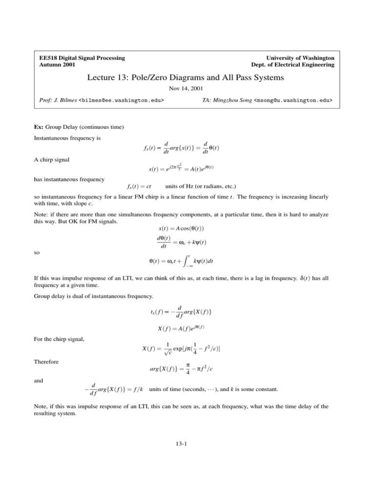
Ex: Group Delay (continuous time)
Instantaneous frequency is
fx (t) ∝
d
d
arg{x(t)} = θ(t)
dt
dt
A chirp signal
x(t) = e j2π
has instantaneous frequency
fx (t) = ct
ct 2
2
= A(t)e jθ(t)
units of Hz (or radians, etc.)
so instantaneous frequency for a linear FM chirp is a linear function of time t. The frequency is increasing linearly
with time, with slope c.
Note: if there are more than one simultaneous frequency components, at a particular time, then it is hard to analyze
this way. But OK for FM signals.
x(t) = A cos(θ(t))
dθ(t)
= ωc + kψ(t)
dt
so
θ(t) = ωct +
Z t
−∞
kψ(t)dt
If this was impulse response of an LTI, we can think of this as, at each time, there is a lag in frequency. δ(t) has all
frequency at a given time.
Group delay is dual of instantaneous frequency.
tx ( f ) ∝ −
d
arg{X( f )}
df
X( f ) = A( f )e jθ( f )
For the chirp signal,
1
1
X( f ) = √ exp[ jπ( − f 2 /c)]
c
4
Therefore
arg{X( f )} =
and
−
d
arg{X( f )} = f /k
df
π
− π f 2 /c
4
units of time (seconds, · · · ), and k is some constant.
Note, if this was impulse response of an LTI, this can be seen as, at each frequency, what was the time delay of the
resulting system.
13-1
13-2
13.1 Frequency Response of Single Zero and Pole Systems
When there is only single zero and pole, we have either
H(z) =
or
1
1 − az−1
H(z) = 1 − az−1
where
a = re jθ
is a general complex number.
Rational z-transforms and FT’s
For
H(e jω ) =
we might want the magnitude squared
− jω )
b0 ∏ M
k=1 (1 − ck e
N
a0 ∏k=1 (1 − dk e− jω )
H(e jω )H ∗ (e jω ) = |H(e jω )|2
or plot in dB scale
20 log10 |H(e jω )| = 20 log10
M
N
b0
+ ∑ 20 log10 |1 − ck e− jω | − ∑ 20 log10 |1 − dk e− jω |
a0 k=1
k=1
Also, system response is additive in log domain, i.e.,
20 log10 |Y (e jω )| = 20 log10 |H(e jω )| + 20 log10 |X(e jω )|
which is important and used for Homomorphic processing (useful in automatic speech recognition.)
Phases add in this case
]H(e jω ) = ]
M
N
b0
+ ∑ ][1 − ck e− jω ] − ∑ ][1 − dk e− jω ]
a0 k=1
k=1
zeros add, poles subtract with the phase.
A note on arg and ARG.
−π < ARG[H(e jω )] ≤ π
which is only the “important” part that can have an effect.
arg is the continuous phase.
when
arg[H(e jω )] = θ(ω)
H(e jω ) = |H(e jω )|e jθ(ω)
arg[H(e jω )] = ARG[H(e jω )] + 2πr(ω)
For some applications, r(ω) takes on integer values.
Note
ARG[H(e jω )] = tan−1
HI (e jω )
HR (e jω )
Now we look at the individual factors: 1 − re jθ e− jω .
|1 − re jθ e− jω |2 = (1 − re jθ e− jω )(1 − re− jθ e jω ) = 1 + r2 − 2r cos(ω − θ)
13-3
Also,
ARG[1 − re jθ e− jω ] = tan−1
and
grd[1 − re jθ e− jω ] =
r sin(ω − θ)
1 − r cos(ω − θ)
r2 − r cos(ω − θ)
1 + r2 − 2r cos(ω − θ)
For a system of single zero/pole and r ≈ 0.9, its magnitude and phase responses and group delay is shown in Fig 13.1.
20 log10 |1 − re jθ e− jω |
PSfrag replacements
0 θ
ω
θ
π
π+θ
2π 2π + θ
π
π+θ
2π 2π + θ
phase in radian
v1
v2
v3
φ3
1
0 θ
−1
group delay (in samples)
0 θ
π
2π 2π + θ
π+θ
Figure 13.1: Frequency domain responses of a single zero/pole system.
Geometrical view of frequency response as viewed from the poles, zeros on the z-plane
Consider a single zero system
H(z) = 1 − re jθ z−1 =
z − re jθ
z
0<r<1
The geometric view of H(z) is shown in Fig 13.2.
v1 =e jω
v2 =re jθ
v3 =v1 − v2 = e jω − re jθ
So
1 − re jθ e− jω =
e jω − re jθ
v1 − v 2
v3
=
=
e jω
v1
v1
Then
|1 − re jθ e− jω | =
|v3 |
= |v3 |
|v1 |
since |v1 | = 1. The length of v3 tells us the absolute value of the magnitude of the response.
Note:
13-4
v3
v2 θ
PSfrag replacements
v1
ω
π
φ3
Figure 13.2: Geometric view. Think about as rubber band at the zero, and at z = 0. Streched to current position on
unit circle.
1. This is not even at ω = 0, when time signal is complex. If θ = 0, magnitude would be even and time signal
would be real.
2. v3 is called a “zero” vector. If we had a pole, we would have a pole vector. We can generalize.
To get magnitude response at a given ω:
• multiply all zero vector lengths
• multiply all pole vector lengths
• divide the result (i.e., divide by all pole vectors)
in dB domain, add log zero vector lengths and subtract log pole vector lengths.
What about phase?
As shown in Fig 13.3,
φ3
v3
v2 θ
PSfrag replacements
v1
ω
π
Figure 13.3: Geometric view of phase.
13-5
](1 − re jθ e− jω ) =](e jω − re jθ ) − ]e− jω
=]v3 − ]v1
=φ3 − ω
Consider an example as shown in Fig 13.4, where
θ = π,
r<1
So, as ω increases, |v3 | will get smaller until ω = π, where |v3 | will be the minimum and after ω > π, |v3 | gets larger
v1
v3
PSfrag replacements
φ3
ω
v2
θ
π
Figure 13.4: An example.
again.
In general, zero at re jθ =⇒ |v3 |. From that zero will be the smallest at ω = θ (that is the closest zero to the unit circle
at that point.)
For phase,
• for ω < π, we have ω > φ3 , so that phase is negative.
• at ω = π, we have φ3 = ω, so zero phase there (at minimum magnitude.)
• at ω > π, we have φ3 > ω, so positive phase.
This works for other θ’s as well, i.e., phase sign shift and minimum amplitude magnitude at ω = θ.
When r → 1, what happens?
When r → 1, it is possible for v1 = v2 ⇒ v3 = 0. Hence magnitude is zero at ω = θ, as expected. (zero on the unit
circle should give zero magnitude).
What about the phase?
At ω = θ, the phase is θ3 − ω.
When ω < θ, the phase is shown in Fig 13.5.
When ω > θ, the phase is shown in Fig 13.6.
So v3 is going to flip sign instantaneously when ω = θ − ∆ and ω = θ + δ. This gives what is shown in Fig 13.7.
13-6
φ3
v3
v1
v2
θ
PSfrag replacements
ω
π
Figure 13.5: ω < θ.
v1
φ3
v3
θ
PSfrag replacements
v2
ω
π
Figure 13.6: ω > θ.
PSfrag replacements
ω
π
v1
v2
v3
φ3
radian
1
−1
θ
Figure 13.7: Phase sign flip when r > 1. When r ≤ 1, the phase is smooth.
13-7
Relationship between magnitude and phase
For rational system function, there are constraints on magnitude and phase (unlike in general system)
How to tell?
|H(e jω )|2 = H(e jω )H ∗ (e jω ) = H(z)H ∗ (1/z∗ )|z=e jω
If
−1
b0 ∏ M
k=1 (1 − ck z )
a0 ∏Nk=1 (1 − dk z−1 )
H(z) =
Note: zero at z = ck = |ck |e j∠ck .
Note: zero at z = 1/c∗k =
1 j∠ck
.
|ck | e
H ∗ (1/z∗ ) =
∗
b0 ∏ M
k=1 (1 − ck z)
N
a0 ∏k=1 (1 − dk∗ z)
Poles and zeros reflect across unit circle.
Define
C(z) =
b0
a0
2
−1
∗
∏M
k=1 (1 − ck z )(1 − ck z)
N
∏k=1 (1 − dk z−1 )(1 − dk∗ z)
For C(z), pole/zero at z = a implies pole/zero at z = 1/a∗ . But C(z) could come from other H(z) with same magnitude
response but different phase response.
The key is: given a magnitude response of a linear constant coefficient difference equation system, there exist some
finite number of possible phase responses, and correspondingly to different systems (some might be stable/causal,
while others do not).
13.2 All Pass System
Consider
H(z) =
z−1 − a∗
1 − az−1
with pole at z = a and zero at z = 1/a∗ , where a = re jθ . Then
H(e jω ) =
so
1 − a∗ e jω
e− jω − a∗
= e− jω
−
jω
1 − ae
1 − ae− jω
|H(e jω )| = 1

