Electronic voltage regulator
Eaton’s EVR microprocessor-controlled
tap changer (10–500 kVA, three-phase)
Overview
EVR features
The appropriate transformer
tap is automatically activated
through a silicon-controlled
rectifier (SCR), maintaining a
tightly regulated output voltage.
Tap changes are initiated within
one electrical cycle—switching
at zero current crossing to
ensure a minimum amount of
noise during tap transitions.
•
±3% voltage output for a
+10/–23% voltage input
•
Power factor—the EVR is not
affected by load power factor
•
Total harmonic distortion
(THD)—the EVR adds less
than 1% added to the output
waveform under any dynamic
linear loading conditions
presented to the line regulator
•
High efficiency—97%
•
Wide input frequency range
—the EVR operates within a
broad input frequency range
of 57–63 Hz
•
Integral manual rotary
maintenance bypass switch
standard on 50–500 kVA units
and optional on smaller units
•
Seven taps per phase used
to provide optimal voltage
regulation
•
Fail-safe bypass circuit, tripleshielded isolation transformer
and overtemperature
protection
•
One-year parts warranty
with no startup required
•
Front-only access required
(50–150 kVA units only)
allows unit to be installed
in tight spaces
Seven taps per phase are used
for optimal voltage regulation.
Also, the EVR is a low output
impedance, shielded isolation
transformer. As a result of the
low impedance, load changes
do not affect other equipment
connecting the system.
The EVR’s unique design
ensures high efficiency at
97% and 1000% in-rush
capability. It is equipped with
a thermal-magnetic breaker
that allows for proper system
coordination to prevent
nuisance trips.
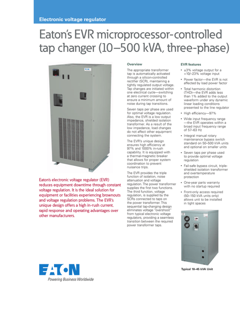
Eaton’s electronic voltage regulator (EVR)
reduces equipment downtime through constant
voltage regulation. It is the ideal solution for
equipment or facilities experiencing brownouts
and voltage regulation problems. The EVR’s
unique design offers a high in-rush current,
rapid response and operating advantages over
other manufacturers.
The EVR provides the triple
function of isolation, noise
attenuation and voltage
regulation. The power transformer
supplies the first two functions.
The third function, voltage
regulation, is supplied by the
SCRs connected to taps on
the power transformer. This
sequential tap-changing design
eliminates voltage “overshoot”
from typical electronic voltage
regulators, providing a seamless
transition between the required
power transformer taps.
Typical 10–45 kVA Unit
EVR Specifications
Technology
Input voltages
Input voltage range
Output voltage
Response time
Frequency
Efficiency
Line regulation
Load regulation
Correction time
Harmonic distortion
Electronic tap changer
208–600V, three-phase (three-wire)
+10% to –23% of nominal rated input
±3% of nominal
1/2 cycle
60 Hz, ±3%
97% typical
Output is ±3% of nominal for input variations of +10% to –23% of nominal
Output is maintained within 3% of nominal from no load to full load
Output will be corrected to within ±3% of nominal in 1.5 cycles or less
Less than 1.0% added to the output waveform under any dynamic linear loading conditions
presented to the line regulator
Noise attenuation
Common mode
Normal mode
Turn-on characteristics
Overload rating
Ambient rating
Monitoring
Surge protection (optional)
Input breaker
Bypass switch
Metering (optional)
For custom design, call the
support number below.
Application support
If you are having trouble understanding a problem related to
power quality, reliability or
energy management, call an
application engineer at
800-809-2772 (option 4,
sub-option 2).
146 dB
3 dB down at 1000 Hz, 40 dB/decade to below 50 dB with resistive load
When energized, voltage overshoot will be less than 5% of nominal for 1 cycle or less
1000% for 1 cycle and 200% for 10 seconds
–10° to 40°C
Three green LEDs (phase power on indication), one red LED (alert indication)
CVX 50 kA SPD device 50 kVA and below, CVX 100 kA SPD device 75 kVA and above
MCCB rated 125% of full rated current
Normal and bypass selector
Standard metering (IQ 130)—voltage and current with minimum and maximum
Premium metering (IQ 150)—voltage, current, frequency, power, energy, PF, with minimum
and maximum, communications capabilities
1-year parts
Warranty
EVR ordering guidelines
EVR XXX XXXX XXXX X X XX X
kVA Ratings and Dimensions
kVA
Weight
(lbs)
BTUs/
hr
Bypass
Cabinet Size
Metering Dimensions H x W x D in Inches (mm)
010
010
015
015
025
030
045
050
075
100
125
150
225
300
500
440
520
465
700
700
720
950
1,176
1,575
2,014
2,137
2,240
3,300
4,000
5,500
1,025
1,205
1,540
1,540
2,560
3,090
4,600
7,332
9,514
11,833
14,748
17,698
23,000
30,750
51,250
Optional
Optional
Optional
Optional
Optional
Optional
Optional
Yes
Yes
Yes
Yes
Yes
Yes
Yes
Yes
No
Yes
No
Yes
Yes
Yes
Yes
Yes
Yes
Yes
Yes
Yes
Yes
Yes
Yes
Options
30.20 x 22.20 x 29.00 (767.1 x 563.9 x 736.6)
44.20 x 22.20 x 29.00 (1122.7 x 563.9 x 736.6)
30.20 x 22.20 x 29.00 (767.1 x 563.9 x 736.6)
44.20 x 22.20 x 29.00 (1122.7 x 563.9 x 736.6)
44.20 x 22.20 x 29.00 (1122.7 x 563.9 x 736.6)
44.20 x 22.20 x 29.00 (1122.7 x 563.9 x 736.6)
44.30 x 45.90 x 29.00 (1125.2 x 1165.9 x 736.6)
66.00 x 29.00 x 35.50 (1676.4 x 736.6 x 901.7)
76.00 x 34.40 x 35.50 (1930.4 x 873.8 x 901.7)
76.00 x 34.40 x 35.50 (1930.4 x 873.8 x 901.7)
76.00 x 34.40 x 35.50 (1930.4 x 873.8 x 901.7)
76.00 x 34.40 x 35.50 (1930.4 x 873.8 x 901.7)
77.40 x 56.00 x 41.50 (1966.0 x 1422.4 x 1054.1)
77.40 x 56.00 x 41.50 (1966.0 x 1422.4 x 1054.1)
77.00 x 72.40 x 48.40 (1955.8 x 1839.0 x 1229.4)
B =Bypass switch A
M1=Standard metering (IQ 130)
M2=Premium metering (IQ 150)
Nominal Input Voltage
Delta Input: L, L, L, G
208D = 208
240D = 240
400D = 400
480D = 480
600D = 600
Nominal Output Voltage
Wye Output: L, L, L, N, G
Surge Protection
X = No
S = Yes
Frequency
A = 60 Hz
B = 50 Hz
208Y = 120/208
400Y = 230/400
480Y = 277/480
600Y = 347/600
A Bypass is standard on 50 kVA and larger units and an option on 45 kVA and smaller units. The ‘B’ is not included in the part number for units 50 kVA and larger.
Eaton
1000 Eaton Boulevard
Cleveland, OH 44122
United States
Eaton.com
© 2013 Eaton
All Rights Reserved
Printed in USA
Publication No. PA01002001E / Z13842
August 2013
Eaton is a registered trademark.
All other trademarks are property
of their respective owners.


