DPT Series
LED Post Top Luminaire
IMPORTANT SAFEGUARDS
INSTALLATION INSTRUCTIONS
INSTRUCTIONS D’INSTALLATION
When using electrical equipment, basic safety precautions should always be
followed including the following:
READ AND FOLLOW ALL SAFETY
INSTRUCTIONS
1. DANGER- Risk of shock- Disconnect power before installation.
DANGER – Risque de choc – Couper l’alimentation avant
l’installation.
2. This luminaire must be installed in accordance with the NEC or your
local electrical code. If you are not familiar with these codes and
requirements, consult a qualified electrician.
Ce produit doit être installé conformément à NEC ou votre code
électrique local. Si vous n’êtes pas familier avec ces codes et ces
exigences, veuillez contacter un électricien qualifié.
SAVE THESE INSTRUCTIONS FOR
FUTURE REFERENCE
TO INSTALL:
STEP 1:
1
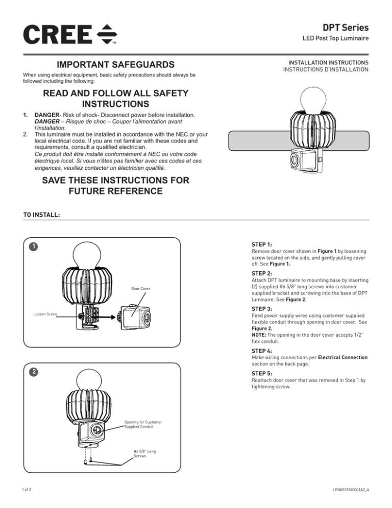
Remove door cover shown in Figure 1 by loosening
screw located on the side, and gently pulling cover
off. See Figure 1.
STEP 2:
Door Cover
Attach DPT luminaire to mounting base by inserting
(2) supplied #6 5/8" long screws into customer
supplied bracket and screwing into the base of DPT
luminaire. See Figure 2.
STEP 3:
Loosen Screw
Feed power supply wires using customer supplied
flexible conduit through opening in door cover. See
Figure 2.
NOTE: The opening in the door cover accepts 1/2"
flex conduit.
STEP 4:
Make wiring connections per Electrical Connection
section on the back page.
2
STEP 5:
Reattach door cover that was removed in Step 1 by
tightening screw.
Opening for Customer
Supplied Conduit
#6 5/8" Long
Screws
1 of 2
LPN00253X0001A0_A
ELECTRICAL CONNECTIONS
STEP 1:
Make the following electrical connections to the terminal block:
For 208/240 applications, make the following Electrical Connections to
the terminal block:
a. Connect L2 (Hot) supply lead to the black lead.
b. Connect L1 (Hot) supply lead to the white lead
c. Connect the green or green/yellow ground lead to the supply
ground lead
LUMINAIRE
TERMINAL
BLOCK
BLACK
OR L2 (HOT)
SUPPLY WIRING
For 120/277V applications make the following Electrical Connections to
the terminal block:
a. Connect the black lead to the voltage supply lead
b. Connect the white lead to the neutral supply lead
c. Connect the green or green/yellow ground lead to the supply
ground lead
GREEN
WHITE
OR L1 (HOT)
LINE-BLACK
GROUND-GREEN
NEUTRAL-WHITE
© 2015 Cree, Inc. All rights reserved. For informational purposes only. Content is subject to change.
See www.cree.com/canada for warranty and specifications. Cree® is a registered trademark, and the Cree logo is a trademark
of Cree, Inc.
cree.com/canada
2 of 2
LPN00253X0001A0_A

