XP SEMICONDUCTOR (AC) FUSES
advertisement

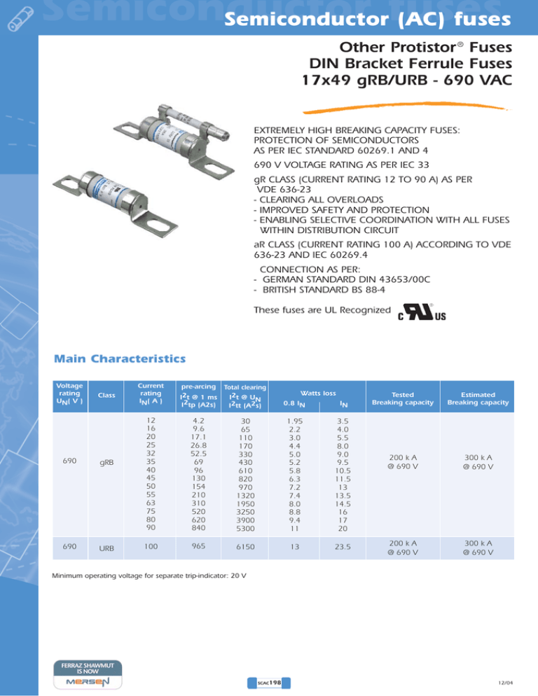
Semiconductor Semiconductorfuses (AC) fuses Other Protistor ® Fuses DIN Bracket Ferrule Fuses 17x49 gRB/URB - 690 VAC EXTREMELY HIGH BREAKING CAPACITY FUSES: PROTECTION OF SEMICONDUCTORS AS PER IEC STANDARD 60269.1 AND 4 690 V VOLTAGE RATING AS PER IEC 33 gR CLASS (CURRENT RATING 12 TO 90 A) AS PER VDE 636-23 - CLEARING ALL OVERLOADS - IMPROVED SAFETY AND PROTECTION - ENABLING SELECTIVE COORDINATION WITH ALL FUSES WITHIN DISTRIBUTION CIRCUIT aR CLASS (CURRENT RATING 100 A) ACCORDING TO VDE 636-23 AND IEC 60269.4 CONNECTION AS PER: - GERMAN STANDARD DIN 43653/00C - BRITISH STANDARD BS 88-4 These fuses are UL Recognized Main Characteristics Voltage rating UN( V ) Class 690 gRB 690 URB Current rating IN( A ) I2t @ 1 ms I2tp (A2s) Total clearing I2t @ UN I2tt (A2s) 12 16 20 25 32 35 40 45 50 55 63 75 80 90 4.2 9.6 17.1 26.8 52.5 69 96 130 154 210 310 520 620 840 30 65 110 170 330 430 610 820 970 1320 1950 3250 3900 5300 1.95 2.2 3.0 4.4 5.0 5.2 5.8 6.3 7.2 7.4 8.0 8.8 9.4 11 3.5 4.0 5.5 8.0 9.0 9.5 10.5 11.5 13 13.5 14.5 16 17 20 100 965 6150 13 23.5 pre-arcing Watts loss 0.8 IN IN Tested Breaking capacity Estimated Breaking capacity 200 k A @ 690 V 300 k A @ 690 V 200 k A @ 690 V 300 k A @ 690 V Minimum operating voltage for separate trip-indicator: 20 V SCAC198 12/04 Semiconductor fuses Semiconductor (AC) fuses Other Protistor ® Fuses DIN Bracket Ferrule Fuses 17x49 gRB/URB - 690 VAC German standard without blown fuse indication 46.2 18.5 1.5 96 69.4 - 81 8.73 16 ø18 Weight: 42 g Packaging: 10 pieces 15.5 German standard with separate trip-indicator DIN 43623/00C 24.4 1.5 46.2 96 69.4 - 81 27 8.73 16 Weight: 55 g Packaging: 10 pieces 15.5 7 82.7 British standard without blown fuse indication 46.2 18.5 2 77.2 61 - 65.5 12.7 7.14 ø18 Weight: 40 g Packaging: 10 pieces 9.5 British standard with separate trip-indicator BS 88-4 24 2 46.2 77.2 61 - 65.5 27 12.7 7.14 7 12/04 74 9.5 Weight: 60 g Packaging: 3 pieces Current rating 12 16 20 25 32 35 40 45 50 55 63 75 80 90 100 Designation 6,9 gRB 17 D08/12 6,9 gRB 17 D08/16 6,9 gRB 17 D08/20 6,9 gRB 17 D08/25 6,9 gRB 17 D08/32 6,9 gRB 17 D08/35 6,9 gRB 17 D08/40 6,9 gRB 17 D08/45 6,9 gRB 17 D08/50 6,9 gRB 17 D08/55 6,9 gRB 17 D08/63 6,9 gRB 17 D08/75 6,9 gRB 17 D08/80 6,9 gRB 17 D08/90 6,9 URB 17 D08/100 Current rating 12 6,9 16 6,9 20 6,9 25 6,9 32 6,9 35 6,9 40 6,9 45 6,9 50 6,9 55 6,9 63 6,9 75 6,9 80 6,9 90 6,9 100 6,9 Current rating 12 16 20 25 32 35 40 45 50 55 63 75 80 90 100 Current rating 12 16 20 25 32 35 40 45 50 55 63 75 80 90 100 SCAC199 Designation gRB 17 D08P 12 gRB 17 D08P 16 gRB 17 D08P 20 gRB 17 D08P 25 gRB 17 D08P 32 gRB 17 D08P 35 gRB 17 D08P 40 gRB 17 D08P 45 gRB 17 D08P 50 gRB 17 D08P 55 gRB 17 D08P 63 gRB 17 D08P 75 gRB 17 D08P 80 gRB 17 D08P 90 URB 17 D08P 100 Designation 6,9 gRB 17/12 6,9 gRB 17/16 6,9 gRB 17/20 6,9 gRB 17/25 6,9 gRB 17/32 6,9 gRB 17/35 6,9 gRB 17/40 6,9 gRB 17/45 6,9 gRB 17/50 6,9 gRB 17/55 6,9 gRB 17/63 6,9 gRB 17/75 6,9 gRB 17/80 6,9 gRB 17/90 6,9 URB 17/100 Designation 6,9 gRB 17P12 6,9 gRB 17P16 6,9 gRB 17P20 6,9 gRB 17P25 6,9 gRB 17P32 6,9 gRB 17P35 6,9 gRB 17P40 6,9 gRB 17P45 6,9 gRB 17P50 6,9 gRB 17P55 6,9 gRB 17P63 6,9 gRB 17P75 6,9 gRB 17P80 6,9 gRB 17P90 6,9 URB 17P100 Ref. Number M220972 N220973 P220974 Q220975 R220976 S220977 T220978 V220979 W220980 X220981 Y220982 Z220983 A220984 B220985 C220986 Ref. Number X221004 Y221005 Z221006 A221007 B221008 C221009 D221010 E221011 F221012 G221013 H221014 J221015 K221016 L221017 M221018 Ref. Number W220957 X220958 Y220959 Z220960 A220961 B220962 C220963 D220964 E220965 F220966 G220967 H220968 J220969 K220970 L220971 Ref. Number D220987 E220988 F220989 G220990 H220991 J220992 K220993 L220994 M220995 N220996 P220997 Q220998 R220999 S221000 T221001 Catalog Number DN17GB69V12 DN17GB69V16 DN17GB69V20 DN17GB69V25 DN17GB69V32 DN17GB69V35 DN17GB69V40 DN17GB69V45 DN17GB69V50 DN17GB69V55 DN17GB69V63 DN17GB69V75 DN17GB69V80 DN17GB69V90 DN17UB69V100 Catalog Number DN17GB69V12P DN17GB69V16P DN17GB69V20P DN17GB69V25P DN17GB69V32P DN17GB69V35P DN17GB69V40P DN17GB69V45P DN17GB69V50P DN17GB69V55P DN17GB69V63P DN17GB69V75P DN17GB69V80P DN17GB69V90P DN17UB69V100P Catalog Number BS17GB69V12 BS17GB69V16 BS17GB69V20 BS17GB69V25 BS17GB69V32 BS17GB69V35 BS17GB69V40 BS17GB69V45 BS17GB69V50 BS17GB69V55 BS17GB69V63 BS17GB69V75 BS17GB69V80 BS17GB69V90 BS17UB69V100 Catalog Number BS17GB69V12P BS17GB69V16P BS17GB69V20P BS17GB69V25P BS17GB69V32P BS17GB69V35P BS17GB69V40P BS17GB69V45P BS17GB69V50P BS17GB69V55P BS17GB69V63P BS17GB69V75P BS17GB69V80P BS17GB69V90P BS17UB69V100P Semiconductor Semiconductorfuses (AC) fuses Other Protistor ® Fuses DIN Bracket Ferrule Fuses 17x49 gRB/URB - 690 VAC Total clearing I2t I2t corrective factor K I2t (A2s) 1.2 1 ms (0,2 ms) 1,5 ms (0,3 ms) 2 ms (0,4 ms) 3 ms (0,6 ms) (2 ms) (1,5 ms) (1,3 ms) (1 ms) (0,8 ms) ms ms ms ms ms 8 7 6 5 4 10 ms (5 ms) 10 5 10 ms (2,8 ms) 1.4 1.0 Left: Curve shows variation of total clearing time (I2tt) and total clearing duration Tt as a function of operating voltage U. 0.8 0.6 10 4 0.4 100 A 90 A 80 A 75 A 0.2 63 A 0 55 A 50 A 45 A 40 A 35 A 32 A 10 3 0 400 600 800 U (V) Peak arc voltage Um (V) 25 A 10 2 200 20 A 16A 1600 12 A Left: Curve shows peak value Um of arc voltage which appears across fuse-link as a function of operating voltage U@ cos ϕ = 0.15 1400 10 1200 10 3 10 4 Ip (A) Above: Horizontal curves show for each rated current maximum values of total clearing I2t (I2tt) as a function of prospective current Ip. @ 690 V. cos ϕ = 0.15. Oblique lines indicate total clearing duration Tt and associated pre-arcing duration in brackets. 400 600 700 U (V) Current limitation curves IN=100 A, aR class with CC’ limiting curve. 10 4 IC(A) 5 10 5 Ip Ic = 90A-100A 80 A 75 A 63 A 55 A 50 A 45 A 40 A 35 A 32 A 25 A 20A 16 A 12 A = 4 10 4 Ic C C’ a= 130 A2=0.6 B1= 1.25 B2= 0.6 Cf3= 0.8 2. 5 10 3 10 2 200 Ip 12 t (s) 16 20 25 32 35 35 45 50 55 63 75 80 90 100 Time vs current characteristics 0 2 10 2 10 10 10 33 1 10 -1 10 -22 10 -2 10 -3 10 1 10 10 -4 10 10 2 10 3 Tolerance for mean pre-arcing current ± 9%. 10 4 I (A) 2 10 2 3 10 3 4 5 10 4 Ip (A) Above: Curves show, for each rating, value of peak letthrough current IC as a function of available fault current Ip. Above: Curves indicate, for each rated current, prearcing time vs. R.M.S. pre-arcing current SCAC200 12/04 Semiconductor fuses Semiconductor (AC) fuses Other Protistor ® Fuses DIN Bracket Ferrule Fuses 17x49 gRB/URB - 690 VAC Microswitch DC Application data L/R (ms) 100 Um (V) 90 8.5 80 70 1100 60 1000 50 900 2 40 20 10 800 23 700 30 1 7 31 cosses à souder ou clips 2.8 Above: Curves indicate permissible value of time constant L/R as a function of DC working voltage. Curve 1: Ip ≥ 1,6 IN only for fuses gRB (current rating from 12 to 50 A) Curve 2: Ip ≥ 8 IN for fuses gRB et URB 600 500 400 300 200 400 300 200 0 100 U (V) 100 0 0 MC 6,3 GR 2.5 0 600 Designation Ref. Num. Weight Pack. 500 500 600 10 20 U (V) Y 310015 10 g 3 pieces Electrical characteristics: IN = 3 A - UN = 250 VAC IN = 2 A - UN = 30 VDC Curve indicates peak arc voltage Um which may appear across the fuse terminals at working voltage U. Certain minimum operating voltage/current 20 V-100 mA NEW gR-CLASS t OPTIMAL PROTECTION OF POWER EQUIPMENT Thanks to recent technological developments, Ferraz Shawmut today markets gR-class PROTISTOR® fuses capable of clearing all types of overloads, from low multiples of current ratings up to very high short-circuit currents. Enhanced performance enables these fuses to provide solutions to many previously unsolved problems in power electronics: protection of cables without the use of additional components, protection of equipment from fire hazards, selective coordination of different fuses within a single power distribution installation... t C 100A "aR" 100A "gR" 2h C' 30s 300A Example: 100A aR vs. 100A gR I minimum interrupting current I 110A SELECTIVE COORDINATION aR gR gR-class semiconductor fuses can be utilized in association with gI and gG-class low voltage power distribution fuses of the same current rating, installed upstream. In a “selectively coordinated“ distribution installation, melting is limited to the fuse associated with the faulted circuit, while upstream fuses remain intact. This prevents unnecessary down-time due to power blackouts in nonfaulted branches. Relay gG 100A Example of selective coordination Before gR 100A gR 100A After M M aR-CLASS vs. gR-CLASS FERRAZ SHAWMUT EXPERTISE aR-class fuses feature a high minimum interrupting current as compared with their current rating. The primary time-current characteristic of aR-class fuses is the CC’ curve, above which another protection device must be associated. The gR-class fuse represents considerably improved performance in semiconductor protection. gR-class fuses should be used in the design of low voltage equipment and in the protection of power electronics equipment. Designers can often substitute a gR-class fuse for an aR-class fuse (10x38, 14x51, 22x58, PSC 000 and 17x49 DIN80 or BS 88-4) but the reverse is not true: an aR fuse can never replace a gR fuse. Start protecting your new equipment with gR-class fuses today. The application of gR class fuses, with current ratings less than 100 Amps, offers enhanced protection, safety and reliability, along with reduced risk of replacement errors and assembly costs. SCAC201


