8 Output Time/Photo Controller WTP-4408
advertisement
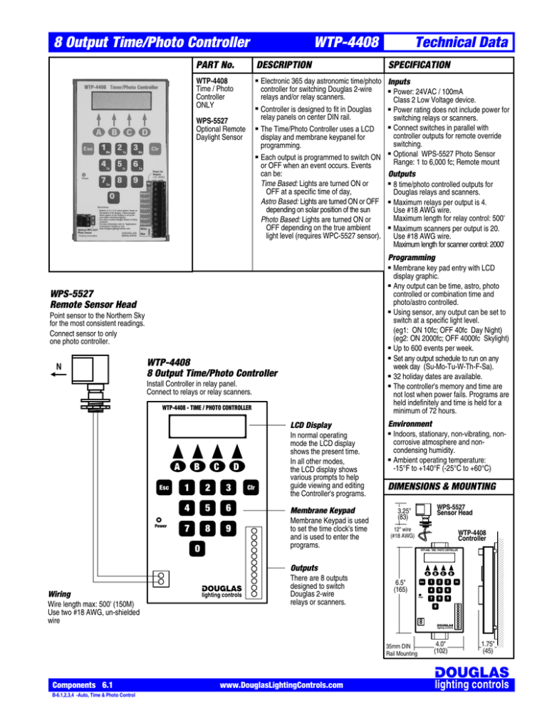
8 Output Time/Photo Controller WTP-4408 PART No. DESCRIPTION WTP-4408 Time / Photo Controller ONLY ■ ■ WPS-5527 Optional Remote Daylight Sensor ■ ■ Technical Data SPECIFICATION Electronic 365 day astronomic time/photo Inputs controller for switching Douglas 2-wire ■ Power: 24VAC / 100mA relays and/or relay scanners. Class 2 Low Voltage device. ■ Power rating does not include power for Controller is designed to fit in Douglas relay panels on center DIN rail. switching relays or scanners. ■ Connect switches in parallel with The Time/Photo Controller uses a LCD controller outputs for remote override display and membrane keypanel for switching. programming. ■ Optional WPS-5527 Photo Sensor Each output is programmed to switch ON Range: 1 to 6,000 fc; Remote mount or OFF when an event occurs. Events can be: Outputs ■ 8 time/photo controlled outputs for Time Based: Lights are turned ON or OFF at a specific time of day, Douglas relays and scanners. Astro Based: Lights are turned ON or OFF ■ Maximum relays per output is 4. depending on solar position of the sun Use #18 AWG wire. Maximum length for relay control: 500' Photo Based: Lights are turned ON or ■ Maximum scanners per output is 20. OFF depending on the true ambient light level (requires WPC-5527 sensor). Use #18 AWG wire. Maximum length for scanner control: 2000' Programming ■ ■ WPS-5527 Remote Sensor Head ■ Point sensor to the Northern Sky for the most consistent readings. Connect sensor to only one photo controller. N ■ ■ WTP-4408 8 Output Time/Photo Controller ■ Install Controller in relay panel. Connect to relays or relay scanners. ■ WTP-4408 - TIME / PHOTO CONTROLLER A Esc Power B C D LCD Display Environment In normal operating mode the LCD display shows the present time. In all other modes, the LCD display shows various prompts to help guide viewing and editing the Controller's programs. ■ 1 2 3 4 5 6 Membrane Keypad 7 8 9 Membrane Keypad is used to set the time clock's time and is used to enter the programs. 0 Clr Membrane key pad entry with LCD display graphic. Any output can be time, astro, photo controlled or combination time and photo/astro controlled. Using sensor, any output can be set to switch at a specific light level. (eg1: ON 10fc; OFF 40fc Day Night) (eg2: ON 2000fc; OFF 4000fc Skylight) Up to 600 events per week. Set any output schedule to run on any week day (Su-Mo-Tu-W-Th-F-Sa). 32 holiday dates are available. The controller's memory and time are not lost when power fails. Programs are held indefinitely and time is held for a minimum of 72 hours. ■ Indoors, stationary, non-vibrating, noncorrosive atmosphere and noncondensing humidity. Ambient operating temperature: -15°F to +140°F (-25°C to +60°C) DIMENSIONS & MOUNTING WPS-5527 Sensor Head 3.25" (83) 12" wire (#18 AWG) WTP-4408 Controller WTP-4408 - TIME / PHOTO CONTROLLER Outputs Wiring Wire length max: 500' (150M) Use two #18 AWG, un-shielded wire lighting controls There are 8 outputs designed to switch Douglas 2-wire relays or scanners. A 6.5" (165) Esc Power B C D 1 2 3 4 5 6 8 9 7 Clr 0 lighting controls 35mm DIN Rail Mounting Components 6.1 B-6.1,2,3,4 -Auto, Time & Photo Control www.DouglasLightingControls.com 4.0" (102) 1.75" (45) 8 Output Time/Photo Controller WTP-4408 Technical Data CONNECTIONS H Breaker Stand Alone Panels 12 Relay Panel Transformer 24VAC W B ■ Relay Lights ■ Sw Sw Sw ■ Individual Occupant Switches Determine how the relays are to be grouped and connect them to the Time/Photo Controller. A maximum of 4 relays can be controlled by each relay output. If occupant control is desired, connect 2-wire switches in parallel with the Controller outputs. If a larger group of relays is to be switched with a Controller output, use a relay scanner (WR-8812 or WR-8824). Connect a Controller output to the switch input of the scanner. Actuating this input will switch all relays connected to the scanner. Connecting a switch to the same input provides a manual occupant override. In panels that have several groups, use a programmable relay scanner (WRS-2224) to permit convenient, keypad assignment of relay groups to a Controller output. Relay Panel H WTP-4408 Breaker B 1 C D 2 3 4 5 2 3 4 7 5 8 6 9 7 08 9 1 Sensor Sensor 0 Maximum 4 relays per WTP-4408 output. 24VAC W B 6 Relays Clr W 1 2 3 4 5 6 7 8 W B Lights 1 2 3 4 5 6 7 8 9 10 11 12 W B WR-8812 Relay Scanner Aux ON Aux Com Aux OFF Douglas Sw Blue Return A Esc 36 Relay Panel Transformer ON OVERRIDE OFF OVERRIDE 6 Time/Photo Controller: Small relay panels For simple automation, connect Controller directly to relays. For occupant control, connect Douglas 2-wire relay switches to the same relay in parallel with the Controller outputs. 1 2 3 4 5 6 7 8 9 10 11 12 FLICK WARN OPTION Time/ Photo Controller: WPS-5527 Remote Sensor (Optional) Large relay panels and relay scanners To expand the number of relays switched by the Controller, use relay scanners. Master switches can be connected in parallel to the Controller outputs to provide a manual override. Sw 1 Sw 4 Sw 2 Sw 5 Sw 3 Sw 6 16 6 18 15 17 7 19 8 20 10 22 12 24 9 21 11 23 NORMAL MODE ON OVERRIDE WRS-2224 Relay Scanner Sw OFF OVERRIDE SELECT MASTER SWITCH 1 2 3 B Inputs 4 5 B Sw WTP-4408 Individual Occupant Switches A B 1 Esc Sw W www.DouglasLightingControls.com C D 2 3 4 5 2 3 4 7 5 8 6 9 7 08 9 1 S e n s o r S e n s o r 24VAC Power Components 6.2 14 4 5 PROGRAM MODE 13 14 15 16 17 18 19 20 21 22 23 24 W B 13 2 3 Master Switch Station Sw B-6.1,2,3,4 -Auto, Time & Photo Control 1 0 6 Clr W 1 2 3 4 5 6 7 8 W B 8 Output Time/Photo Controller WTP-4408 Technical Data CONNECTIONS Multiple Relay Panels ■ ■ ■ Projects that have several panels can be controlled by one Time/Photo Controller signaling relay scanners which in turn switch the relays. A simple wiring strategy is to interconnect the relay panels with a multi-conductor bus. All of the Controller's outputs are then available in each panel. Connect the appropriate output(s) to the relay scanner(s) installed in the panel. Up to 20 scanners can be controlled by each Controller output. The wiring distance for controlling scanners is 2000'. Main Panel W Tr B Optional Remote Sensor (WPS-5527) ■ ■ With no Remote Sensor connected, use the Controller's astronomic features to switch exterior lighting from Dusk-to-Dawn. With a Remote Sensor connected, use Controller's keypad to set specific light levels for each Controller output to be switched. Point Sensor to the northern sky for most consistent readings. Lights Rly Lights Rly Lights Rly WR-8812 or WR-8824 Scanners w B Rly Sw B ■ Rly Rly Rly Rly Rly Rly 6 Rly Remote Panel Remote Panel Tr Tr Lights Rly Lights Rly Lights Rly Rly Lights Rly Rly Lights Rly Lights WR-8812 WR-8824 Scanner Rly Rly Lights Rly Rly Lights Rly Rly Lights Rly Lights Lights Rly Rly Lights Rly Rly Rly Rly Rly WRS-2224 Scanner Sw Rly Lights Sw Rly Lights Sw Rly Lights Lights Rly Lights Rly Lights Rly WRS-2224 Scanner w B B54B321 Individual Occupant Switches Rly Rly Rly Rly Rly Rly Rly Rly Rly Rly Rly Rly Rly Rly Rly Lights Rly Rly Lights Rly Rly Lights Rly Rly Sw Rly Rly Sw Rly Rly Rly 12345678 WB 12345678 WB WPS-5527 Remote Sensor (Optional) W Master Switch Station 1 4 7 2 5 8 WTP-4408 A B 1 3 Esc 6 A 10 conductor bus will provide complete access to all 8 Time/Photo Controller outputs plus the 24V signal power and return. To provide convenient override, connect a master switch station in parallel with the 8 Time/Photo outputs. Components 6.3 B-6.1,2,3,4 -Auto, Time & Photo Control www.DouglasLightingControls.com D 3 2 3 5 8 6 9 7 08 9 5 4 7 S e n s o r S e n s o r Inter-connected Panels C 2 1 4 Clr 6 W 1 2 3 4 5 6 0 7 W 8 B Global Xfmr W Tr B 8 Output Time/Photo Controller OPTIONAL REMOTE SENSOR First determine what the relay groups are and number them. ■ Ensure that the WTP-4408's outputs are correctly connected to the relay groups - either a direct connection to a relay or a connection to a relay scanner controlling a group of relays. ■ Manually actuate an output with the time Controller's override function. Use this feature to test the connections. PROGRAMMING ■ ■ ■ ■ The following completed table represents a typical Light Industrial Office Building utilizing 5 of the timer's outputs. The Instruction Manual provided with the WTP-4408 includes blank programming schedules. Photocopy these schedules and make up tables similar to those shown below. Refer to the Instruction Manual for detailed programming directions. ■ The sensor (WPS-5527) is weatherproof and is designed to withstand harsh climate. However, when possible mount the sensor either indoors pointing outward or in a sheltered area. The sensor's measurements will be less affected by dirt, ice or snow build-up. If mounting outdoors, try to shelter the sensor from the elements. For example, mount the sensor on the underside of the junction box. The sensor has a plastic mounting nipple that can be threaded to a 1/2" pipe thread. A mounting nut is also supplied to suit mounting to a 1/2" knock-out. N Do not mount the sensor so that artificial light shines directly upon it. WALL ■ ■ Technical Data Junction Box INSTALLATION WTP-4408 Time / Photo Controller Schedule Comments Channel 1 - Office Area - Lobby & Corridors Event Day of the Week First employee starts at 7:30am. Turn Lobby lights ON prior to first arrival 07:15 - ON Last employee leaves at 6:45pm. Turn Lobby lights OFF after last departure 19:00 - OFF M, T, W, T, F, -, M, T, W, T, F, S, S Repeat OFF sweeps ensure that lights will be turned OFF even if they are manually switched ON 21, 23, 1, 3, 5 - OFF M, T, W, T, F, S, S Event Day of the Week Employees can turn their own individual lights ON as they arrive no event -, -, -, -, -, -, - Last employee leaves at 6:45pm. Turn Office lights OFF after last departure 19:00 - OFF M, T, W, T, F, S, S Repeat OFF sweeps ensure that lights will be turned OFF even if they are manually switched ON 21, 23, 1, 3, 5 - OFF M, T, W, T, F, S, S Event Day of the Week Shipping/Receiving opens at 7:00am. Ensure high bay HID lights are ON 06:30 - ON M, T, W, T, F, -, - Shipping/Receiving closes at 4:30pm. Turn high bay lights OFF an hour after closing. 17:30 - OFF M, T, W, T, F, S, S Repeat OFF sweeps ensure that lights will be turned OFF even if they are manually switched ON 19, 21, 23, 1, 3, - OFF M, T, W, T, F, S, S Comments Comments Channel 2 - Office Area - Individually Switched Rooms Channel 3 - Warehouse Lights Channel 4 - Exterior Security Lights Event Day of the Week Turn all Security lights ON when dark Below 30FC - ON M, T, W, T, F, S, S Turn all Security lights OFF when light Above 50 FC - OFF M, T, W, T, F, S, S Event Day of the Week Turn Parking Lot lights ON during weekdays at Dusk Below 20FC - ON M, T, W, T, F, -, - Cleaners leave by 9:30. Turn Parking Lot lights OFF 22:00 - OFF M, T, W, T, F, -, - First employees arrive at 6:45. Turn Parking Lot lights ON before arrival 06:30 - ON M, T, W, T, F, -, - Turn Parking Lot lights OFF at Dawn (if Dawn occurs before 6:30am, lights will not turn ON) Above 30 FC - OFF M, T, W, T, F, -, - Comments Comments Components 6.4 B-6.1,2,3,4 -Auto, Time & Photo Control Channel 5 - Exterior Parking Lot Lights www.DouglasLightingControls.com
