Capacitance and Inductance
advertisement

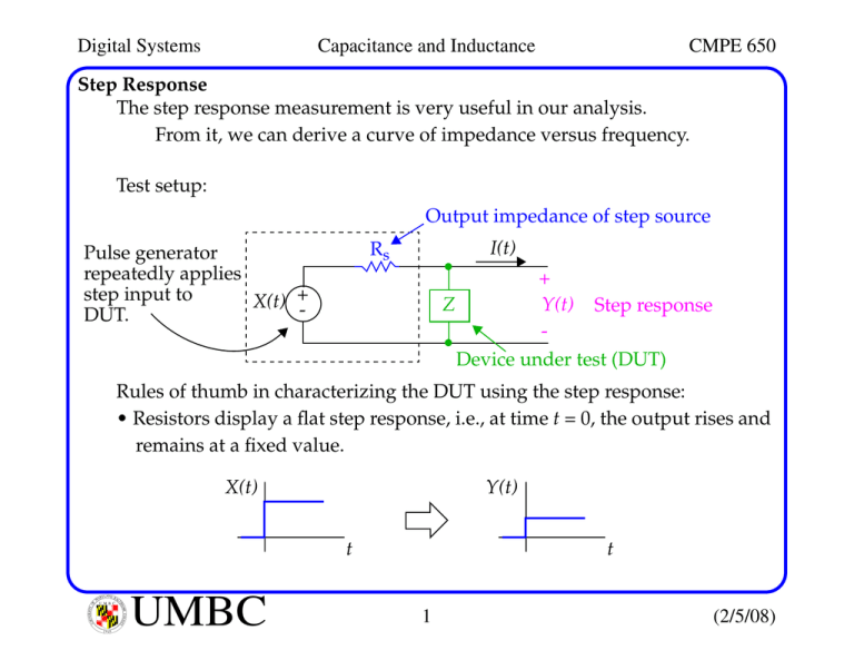
Digital Systems Capacitance and Inductance CMPE 650 Step Response The step response measurement is very useful in our analysis. From it, we can derive a curve of impedance versus frequency. Test setup: Output impedance of step source I(t) Rs Pulse generator repeatedly applies step input to X(t) +DUT. + Z Y(t) Step response Device under test (DUT) Rules of thumb in characterizing the DUT using the step response: • Resistors display a flat step response, i.e., at time t = 0, the output rises and remains at a fixed value. X(t) Y(t) t YLAND BA L U M B C MO UN RE COUNT Y IVERSITY O F AR TI M 1966 UMBC t 1 (2/5/08) Digital Systems Capacitance and Inductance CMPE 650 Step Response • Capacitors display a rising step response, i.e., at time t = 0, the output starts rising and later reaches its full value. X(t) Y(t) t t • Inductors display a sinking step response, i.e., at time t = 0, the output rises instantly to its full value and then later decays back toward 0. X(t) Y(t) t t Capacitors and inductors subdivide into ordinary and mutual categories. Ordinary capacitance and inductance (two-terminal devices) can be a help or hindrance. Mutual capacitance and inductance usually creates unwanted crosstalk. YLAND BA L U M B C MO UN RE COUNT Y IVERSITY O F AR TI M 1966 UMBC 2 (2/5/08) Digital Systems Capacitance and Inductance CMPE 650 Capacitance The capacitor is a 2-terminal element in which the branch voltage and current variables are related by integral and differential equations: t (Voltage on cap depends on history of i) 1 v ( t ) = ---- ∫ i ( τ ) dτ + v ( t 0 ) C t0 and dv i ( t ) = C -----dt Charge and voltage are related by the linear relationship: q q ( t ) = Cv ( t ) slope = C v Power is negative or positive depending on the value of the term v(t)dv/dt in the following expression dv p ( t ) = Cv ( t ) -----dt YLAND BA L U M B C MO UN RE COUNT Y IVERSITY O F AR TI M 1966 UMBC 3 (2/5/08) Digital Systems Capacitance and Inductance CMPE 650 Capacitance But energy (the integral of power) is always positive or zero: 2 Cv ( t ) w ( t ) = ----------------2 Therefore, it’s a passive element (like the resistor) but it is non-dissipative (unlike the resistor). All the energy supplied to the cap. is stored in the electric field. Note that the voltage appearing across a capacitor must always be a continuous function (voltage steps not allowed -- require an infinite i). Current, on the other hand, is allowed to change instantenously. v(t) i(t) i(t) + v(t) - t i(t) t YLAND BA L U M B C MO UN RE COUNT Y IVERSITY O F AR TI M 1966 UMBC 4 t v(t) t (2/5/08) Digital Systems Capacitance and Inductance CMPE 650 Capacitance The energy stored in the electric field of a capacitor is supplied by the driving circuit. Since the driving source is a limited source of power, the voltage takes a finite time to build up. The reluctance of voltage to build up quickly in response to injected power (or decay quickly) is called capacitance. X(t) Rs = 30Ω + Y(t) - I(t) X(t) +- impedance I(t) max value VCC/R Y(t) voltage approaches VCC Y(t) I(t) 1 ns YLAND BA L U M B C MO UN RE COUNT Y IVERSITY O F AR TI M 1966 UMBC 5 short circuit open circuit (2/5/08) Digital Systems Capacitance and Inductance CMPE 650 Capacitance Bear in mind that a capacitor behaves like an inductor at high frequencies (unfortunately). This is due to the mounting leads on capacitors. This inductance causes the step response to have a tiny pulse (a couple hundred ps) at time 0, followed by a drop to 0 and then a capacitive ramp. Note that you will not be able to see this unless your step source rise time is sharp. At Tr, you can characterize the circuit element for frequencies up to: 0.5 F A = ------Tr Reactance on leading edge (to est. distortion in digital wfm by a cap.): Tr X C = ------πC YLAND BA L U M B C MO UN RE COUNT Y IVERSITY O F AR TI M 1966 UMBC 6 (2/5/08) Digital Systems Capacitance and Inductance CMPE 650 Capacitance Test Gig A measurement setup ideal for characterizing capacitors: Pulse generator 50 Ω V(t) +- 50Ω back termination reduces output by 1/2 50 Ω termination 1 square inch 1 KΩ 50 Ω Scope + - 1 KΩ DUT DUT can be a circuit trace, a bypass cap, etc. Note that the resistances are known, so by measuring the rise time of the resulting waveform, the capacitance of the DUT can be computed. The test gig is dimensioned at 1 square inch to ensure it behaves in a lumped fashion. The test gig should include a ground plane of 1 square inch. YLAND BA L U M B C MO UN RE COUNT Y IVERSITY O F AR TI M 1966 UMBC 7 (2/5/08) Digital Systems Capacitance and Inductance CMPE 650 Inductance The inductor is a 2-terminal element in which the branch voltage and current variables are related by integral and differential equations: t 1 i ( t ) = --- ∫ v ( τ ) dτ + i ( t 0 ) L and t0 di v ( t ) = L ----dt Flux linkages (in weber-turns) and current are related by the relationship: λ i n turns of wire slope = L + dλ v ( t ) = -----λ ( t ) = nφ ( t ) = Li ( t ) L v dt i produces flux Power is negative or positive depending on the value of the term i(t)di/dt in the following expression di p ( t ) = i ( t )v ( t ) = i ( t )L ----dt YLAND BA L U M B C MO UN RE COUNT Y IVERSITY O F AR TI M 1966 UMBC 8 (2/5/08) Digital Systems Capacitance and Inductance CMPE 650 Inductance But energy (the integral of power) is always positive or zero: 2 Li ( t ) w ( t ) = --------------2 Therefore, it’s a passive element (like the resistor) but it is non-dissipative (unlike the resistor). All the energy supplied to the ind. is stored in the magnetic field. Note that the current flowing through an inductor must always be a continuous function (current steps not allowed -- require an infinite v). Voltage, on the other hand, is allowed to change instantenously. i(t) v(t) v(t) +- i(t) t v(t) t YLAND BA L U M B C MO UN RE COUNT Y IVERSITY O F AR TI M 1966 UMBC 9 t i(t) t (2/5/08) Digital Systems Capacitance and Inductance CMPE 650 Inductance The energy stored in the magnetic field of a inductor is supplied by the driving circuit. Since the driving source is a limited source of power, the current takes a finite time to build up. The reluctance of current to build up quickly in response to injected power (or decay quickly) is called inductance. X(t) Rs = 30 Ω + Y(t) - I(t) X(t) +- impedance I(t) current approaches VCC/R voltage output decays to 0. Y(t) Y(t) I(t) 1 ns YLAND BA L U M B C MO UN RE COUNT Y IVERSITY O F AR TI M 1966 UMBC 10 open circuit short circuit (2/5/08) Digital Systems Capacitance and Inductance CMPE 650 Inductance Test Gig A measurement setup ideal for characterizing inductors: Pulse generator 50 Ω V(t) +- 50Ω back termination reduces output by 1/2 50 Ω termination 1 square inch Scope + - 39 Ω 10 Ω DUT Reactance on leading edge (to est. distortion in digital wfm by an inductive load: πL X L = ------Tr YLAND BA L U M B C MO UN RE COUNT Y IVERSITY O F AR TI M 1966 UMBC 11 (2/5/08) Digital Systems Capacitance and Inductance CMPE 650 Measuring Inductance Inductance can be measured in a similar way to capacitance by computing the time, for example, in the response waveform to the 63% point. A second method for inductance involves computing the area under the response waveform’s curve: di v ( t ) = L ----dt ∞ ∫ V ind ( t ) dt 0 ∞ dI ind ( t ) = L ∫ ------------------- dt dt 0 ∞ Inductor acts as a short circuit at time (infinity) therefore delta V/RS gives the current. ∆V ∆I = -------RS YLAND BA L U M B C MO UN RE COUNT Y IVERSITY O F AR TI M 1966 UMBC ∫ V ind ( t ) dt = L[I (∞) – I (0)] 0 area = L [ I ( ∞ ) – I ( 0 ) ] ( area )R S area L = ------------ = ----------------------∆I ∆V 12 where RS and ∆V are the open circuit response values (see Example 1.2) (2/5/08) Digital Systems Capacitance and Inductance CMPE 650 Mutual Capacitance Mutual capacitance coupling between two circuits is simply a parasitic capacitor connected between circuit A and circuit B. The coefficient of interaction is in units of farads or amp-seconds/volt. Mutual capacitance CM injects a current IM into circuit B proportional to the rate of change of voltage in circuit A: dV A I M = C M ----------dt This simplification works if: • The coupled current flowing in CM is much smaller than the primary signal current in circuit A, i.e. CM does not load circuit A. • The coupled signal voltage in circuit B is small and can be ignored. Therefore, the voltage difference between A and B is just VA. • The mutual capacitance represents a large impedance compared to the impedance to ground of circuit B. YLAND BA L U M B C MO UN RE COUNT Y IVERSITY O F AR TI M 1966 UMBC 13 (2/5/08) Digital Systems Capacitance and Inductance CMPE 650 Mutual Capacitance A more accurate model uses the difference in voltages between circuits A and B and the loading effect of CM on both circuits. When the coupled noise voltage (crosstalk) is less than 10% of the signal step size (on A), this approximation is accurate to one decimal place. Given: • CM is known. • The rise time Tr and voltage step magnitude VA are known. • The impedance in the receiving circuit, RB, to ground is known. Then crosstalk can be estimated as a fraction of the driving wfm VA. First derive the maximum change in voltage/time of wfm VA: dV A ∆V ----------- = -------dt Tr YLAND BA L U M B C MO UN RE COUNT Y IVERSITY O F AR TI M 1966 UMBC where ∆V is the step height of VA. 14 (2/5/08) Digital Systems Capacitance and Inductance CMPE 650 Mutual Capacitance Second, compute the mutual capacitive current which flows from circuit A to circuit B using: ∆V I M = C M -------Tr (dV/dt) Finally, multiply the interfering current IM by RB to find the interfering voltage (divide by ∆V to express the result as a fractional interference level): CM IM using -------- = --------- given above. ∆V Tr RBC M RB I M Crosstalk = -------------- = ---------------∆V Tr If CM is not known, we can measure it from response wfm. From pulse gen. CM To scope RB = 50 Ω 50 YLAND BA L U M B C MO UN RE COUNT Y IVERSITY O F AR TI M 1966 UMBC 15 (2/5/08) Digital Systems Capacitance and Inductance CMPE 650 Mutual Capacitance We use the area method here as well. area C M = --------------R B ∆V area integrated current = -----------RB (Q=CV) We measure area of voltage wfm. Scope display t (ps/div) then YLAND BA L U M B C MO UN RE COUNT Y IVERSITY O F AR TI M 1966 RB C M Crosstalk = ---------------Tr UMBC 16 (2/5/08) Digital Systems Capacitance and Inductance CMPE 650 Mutual Inductance Whenever there are two loops of current, this is mutual inductance. The coefficient of interaction is in units of heneries or volt-seconds/amp. Mutual inductive coupling between two circuits A and B acts the same as a tiny transformer connecting the circuits. changing current LM low impedance I(t) circuit A RA coupled noise from circuit A circuit B Mutual inductance is usually more problematic than mutual capactance. YLAND BA L U M B C MO UN RE COUNT Y IVERSITY O F AR TI M 1966 UMBC 17 (2/5/08) Digital Systems Capacitance and Inductance CMPE 650 Mutual Inductance The mutual inductance LM injects a noise voltage Y into circuit B proportional to the rate of change in current in A: dI A Y = L M --------dt Once again, this equation is an approximation to the actual coupled noise voltage and is valid under an analogous set of restrictions: • Induced voltage across LM is much smaller than the signal voltage and LM does not load A. • The coupled signal current in B is smaller than the current in A (IA) and therefore, the small coupled current in B can be ignored. • Coupled impedance is small compared to impedance to ground of B. I(t) A YLAND BA L U M B C MO UN RE COUNT Y IVERSITY O F AR TI M 1966 UMBC + Y(t) - B 18 Magnetic flux in B is total magnetic field strength of A over loop. (2/5/08) Digital Systems Capacitance and Inductance CMPE 650 Mutual Inductance Note that voltage induced in loop B is proportional to the rate of change of current in loop A. Also note that a magnetic field is a vector quantity, e.g. flipping loop B reverses the polarity of the flux coupling and induced voltage in B. Given: • LM is known. • The rise time Tr and voltage step magnitude VA are known. • The impedance in the driving circuit, RA, to ground is known. Then crosstalk can be estimated as a fraction of the driving wfm VA. First derive the maximum change in voltage/time of wfm VA: dV A ∆V ----------- = -------dt Tr YLAND BA L U M B C MO UN RE COUNT Y IVERSITY O F AR TI M 1966 UMBC where ∆V is the step height of VA. 19 (2/5/08) Digital Systems Capacitance and Inductance CMPE 650 Mutual Capacitance Second, assume loop A is resistively damped by RA, i.e. current and voltage are proportional to each other. Then, we can relate current to voltage using some well-defined resistance RA: dI A ∆V --------- = -------------dt R AT r (V=IR) Next compute the mutual inductive interference Y, which appears in B: ∆V Y = L M -------------R AT r from dI A Y = L M --------dt Finally, divide by ∆V to express the result as a fractional interference level: LM Crosstalk = -------------R AT r YLAND BA L U M B C MO UN RE COUNT Y IVERSITY O F AR TI M 1966 UMBC 20 (2/5/08)


