Select Interface - Womack Electric Supply
advertisement
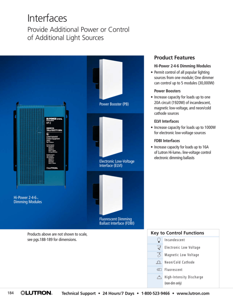
Interfaces Provide Additional Power or Control of Additional Light Sources Product Features Hi-Power 2·4·6 Dimming Modules • Permit control of all popular lighting sources from one module; One dimmer can control up to 5 modules (30,000W) Power Booster (PB) Power Boosters • Increase capacity for loads up to one 20A circuit (1920W) of incandescent, magnetic low-voltage, and neon/cold cathode sources ELVI Interfaces • Increase capacity for loads up to 1000W for electronic low-voltage sources Electronic Low-Voltage Interface (ELVI) FDBI Interfaces • Increase capacity for loads up to 16A of Lutron Hi-lume® line-voltage control electronic dimming ballasts Hi-Power 2·4·6™ Dimming Modules Fluorescent Dimming Ballast Interface (FDBI) Products above are not shown to scale, see pgs.188-189 for dimensions. Key to Control Functions Incandescent E l e c t r o n i c L o w Vo l t a g e M a g n e t i c L o w Vo l t a g e Neon/Cold Cathode Fluorescent High-Intensity Discharge (non-dim only) 184 Technical Support • 24 Hours/7 Days • 1·800·523·9466 • www.lutron.com Wiring Type Key System Wiring TYPE A (2) 12 AWG (120/277V) TYPE B (3) 12 AWG wires (120/277V) Interfaces Standard Distribution Panels 20A Dimmer 120V Power Booster pg.189 20A 120V Dimmer ELVI Interface pg.189 Dimmer FDBI Interface pg.189 20A 120V Hi-Power 2·4·6™, pg.188 HP 2–1 circuit HP 4–2 circuits (phase independent) HP 6–3 circuits (phase independent) OR non-dim OR non-dim OR non-dim 120V/277V To additional HP 2·4·6 Modules Dimmer 120V Control Feed For a complete list of products compatible with interfaces, see pg.187 Fore more detailed wiring diagrams, see Wiring Diagram Index, pg.204 UP Mounting: -7˚ +7˚ • • • • Power boosters/interfaces are not plenum rated and are for indoor use only When mounting several units in vertical layout, allow 4.5” (114mm) between units Power boosters/interfaces must be mounted within 7° of true vertical Power boosters/interfaces generate heat; mount only where ambient temperature will be 0°-40°C (32°-104°F) with a non-condensing relative humidity <90% To Order/Customer Service • 8am–8pm ET (US/CAN) • 1·888·LUTRON1 185 Select Interface by Load Select Interface Power Booster 1 pg.189 Load Type ELVI Interface 2 pg.189 FDBI Interface 1 pg.189 Hi-Power 2·4·6™ 1 per circuit, pg.188 Incandescent 120V 16A, 1920W • • Electronic Low Voltage 120V 8.3A, 1000W • • 3 16A, 1920W (use two) • 3 Magnetic Low Voltage 120V 16A, 1920VA (1500W) 277V 16A, 4432VA (3500W) • • • Neon/Cold Cathode 120V 16A, 1920VA • • Fluorescent Hi-lume® Ballasts 120V 16A Tu-Wire® Ballasts 120V 16A Maximum Per Dimmer • • 2 • • 4 2 2 5 5 1 Each counts as 40W load toward dimmer maximum capacity and meets the minimum load requirement. 2 Each counts as 25W load toward dimmer maximum capacity and meets the minimum load requirement. 3 Approved transformers only, please contact the Lutron Technical Support Center. 4 When used with a GRAFIK Eye® control unit. 5 For best performance, use Faedra™, Maestro®, NovaTa®, Spacer®, Spacer System™, or Vareo®. 186 Technical Support • 24 Hours/7 Days • 1·800·523·9466 • www.lutron.com Select a Control for the Interface Product Ariadni® Power Booster pg.189 ELVI Interface pg.189 — AYF-103P- AYF-103P- AY-600P-, AY-603P- — DVF-103P- DVF-103P- DVSCF-103P- DVSCF-103P- DV-600P-, DV-603PDVSC-600P-, DVSC-603P- — — — FA-600-, FA-600M- — — — GL-600-, GL-600P-, GL-603P- FDBI Interface pg.189 pg.88 Diva® Gloss pg.64 Satin Colors™ Faedra™ pg.82 Glyder® pg.92 GRAFIK Eye® pg.108 Maestro® pg.58 NovaTa® pg.28 Qoto™ 3000 Series 2000 Series Gloss Satin Colors Hi-Power 2·4·6™ per circuit, pg.188 All interfaces wire directly to individual zones on any GRAFIK Eye 3000 Series control unit GRX-2402-, -2403-, -2406MAELV-600MSCELV-600M- — — — — Direct 2000W control with NT-2000- NTF-10-, NTF-103P- MA-600MSC-600M- — — — Q-600P-, Q-603P- RA-6ND- RA-6ND- RA-6ND- RA-6ND- — SF-10PSF-103P- SF-10PSF-103P- S-600-, S-600P-, S-603P- Use Spacer System Use Spacer System Use Spacer System SP-600-, SP-600M- SPSELV-600SPSELV-600M- SPSF-6ASPSF-6AM- SPSF-6ASPSF-6AM- SPS-600-, SPS-600M- — VF-10- VF-10- V-600- Direct 16A control with NT-600-, NT-603PNTF-10-, NTF-103PNTB-600- pg.86 RadioRA® Interfaces Select Interface Use only model numbers listed, Lutron does not recommend use of any other controls shown in this catalog with these interfaces. pg.154 Skylark® pg.70 Spacer® pg.54 Spacer System™ pg.142 Vareo® pg.24 To Order/Customer Service • 8am–8pm ET (US/CAN) • 1·888·LUTRON1 187 Hi-Power 2·4·6 ™ Description non-dim Maximum Capacity Model # Important Information Hi-Power 2·4·6 Dimming Modules Ships in 48 hrs. Incandescent, Magnetic Low Voltage, Electronic Low Voltage, Fluorescent, Neon/Cold Cathode, High-intensity Discharge Hi-Power Dimensions 120V or 277V in one module; not for 100V, 230V, 220-240V; up to 5 modules can be daisy-chained for greater capacity. Hi-Power 2 1 Circuit HP-2 120/277V Product Above: The load circuit capacity by source and voltage is detailed below. Hi-Power 2 dimming modules control the lights based upon control input from a single 120V dimmer. Requires a single 120V control feed for dimmer and a phase independent 120/277V load feed. Minimum load is 50W. Hi-Power 4 2 Circuits HP-4 120/277V Product Above: The load circuit capacity by source and voltage is detailed below. Hi-Power 4 dimming modules control the lights based upon control input from a single 120V dimmer. Requires a single 120V control feed for dimmer and two phase independent 120/277V load feeds. Minimum load is 50W per circuit. Hi-Power 6 3 Circuits HP-6 120/277V Product Above: The load circuit capacity by source and voltage is detailed below. Hi-Power 6 dimming modules control the lights based upon control input from a single 120V dimmer. Requires a single 120V control feed for dimmer and three 120/277V load feeds. Maximum heat dissipation is 600 Btu/hr. Minimum load is 50W per circuit. W: 10.38” (264mm) H: 14.50” (368mm) D: 5.75” (146mm) wt: 15lb (6.8kg) Surface Mount Hi-Power Maximum Heat Dissipation HP-2: 200Btu/hr HP-4: 400Btu/hr HP-6: 600Btu/hr Installation Modules make an audible noise, mount where acceptable. For More Information: www.lutron.com/hipower246 Fax-on-Demand 1·800·523·9466 Load Capacity per Circuit–Dimmed or Switched (Not to exceed N.E.C. capacity rating; control voltage is always 120V) 188 Source Dimmed (120V) Switched (120V) Dimmed (277V) Switched (277V) Incandescent 16A, 1920W/VA 10A, 1200W/VA Electronic Low Voltage 16A, 1920W/VA 10A, 1200W/VA Magnetic Low Voltage 16A, 1920W/VA 10A, 1200W/VA 16A, 4432W/VA not available Fluorescent (Hi-lume® ) 16A, 1920W/VA 16A, 1920W/VA 16A, 4432W/VA not available Fluorescent (Tu-Wire® ) 16A, 1920W/VA 16A, 1920W/VA Fluorescent (magnetic ballasts) not available 16A Fluorescent (electronic ballasts) not available 10A Neon/Cold Cathode 16A, 1920W/VA 10A, 1200W/VA High-Intensity Discharge not available 10A, 1200W/VA Technical Support • 24 Hours/7 Days • 1·800·523·9466 • www.lutron.com Power Boosters, Interfaces Description Maximum Capacity Model # Incandescent, Magnetic Low Voltage, Neon/Cold Cathode, Fluorescent with Tu-Wire® Dimming Ballast 120V 2000W/VA NGRX-PB-WH • Can switch (non-dim) all of the sources mentioned above • Up to two interfaces per dimmer Product Above: All voltages indicated are phase-to-neutral. Load circuit feed is phase independent of control circuit from dimmer. Only available in white. For compatible controls, see pg.187. Interfaces Electronic Low-Voltage Interface 120V 1000W ELVI-1000 • Uses reverse phase-control necessary for dimming of electronic transformer supplied low-voltage lighting • Up to two interfaces per dimmer Product Above: All voltages indicated are phase-to-neutral. Load circuit feed is phase independent of control circuit from dimmer. Only available in white. For compatible controls, see pg.187. Fluorescent Dimming Ballast Interface 120V 16A GRX-FDBI-16A-120 • Allows dimming of Lutron Hi-lume® line-voltage control electronic dimming ballasts (Please refer to the Lutron Fluorescent Dimming Systems Selection Guide, P/N 366-002, or visit www.lutron.com for more information) • Up to two interfaces per dimmer Product Above: All voltages indicated are phase-to-neutral. Load circuit feed is phase independent of control circuit from dimmer. Only available in white. Not to be used for switching. For compatible controls, see pg.187. Interface Selection Guide For a complete list of compatible interfaces and controls, see pg.187. Ships in 48 hrs. Interfaces Power Boosters Important Information Power Booster/Interface Wallplate Dimensions W: 4.56” (116mm) H: 4.56” (116mm) D: 0.69” (18mm) Wallbox Size: 2-Gang, 3.5” (89mm) deep Power Booster/Interface Wiring and Installation All power boosters and interfaces should be connected to the same neutral. This neutral should not be shared with any other controls or with the lighting load. Lamp Debuzzing Coil Installation Mounts on 4”x 4” x 1.5” junction box. LDCs make an audible buzz; mount in remote area (e.g., an electrical closet, or a basement.) Not for use with electronic low-voltage or fluorescent loads; reverse phase-control products; or with Spacer System™, Spacer®, Maestro®, or Faedra™ dimmers. Not plenum rated. Lamp Debuzzing Coils (LDC) An effective way of reducing lamp filament buzz. 120V 277V LDC 100W – 200W 100W – 450W LDC-1.7-TCP LDC 200W – 400W 450W – 900W LDC-3.3-TCP LDC 400W – 800W 900W – 1500W LDC-6.7-TCP LDC 600W – 1200W — LDC-10-TCP LDC 1200W – 1920W — LDC-16-TCP Products Above: Use one LDC per dimmer. LDCs may be wired in series with the dimmer on its line side or load side. UL listed and thermally protected. Do not overload LDC. For More Information: www.lutron.com/grafikeye/grspec Fax-on-Demand 1·800·523·9466 To Order/Customer Service • 8am–8pm ET (US/CAN) • 1·888·LUTRON1 189
