Session 4P7 Extended/Unconventionl Electromagnetic
advertisement
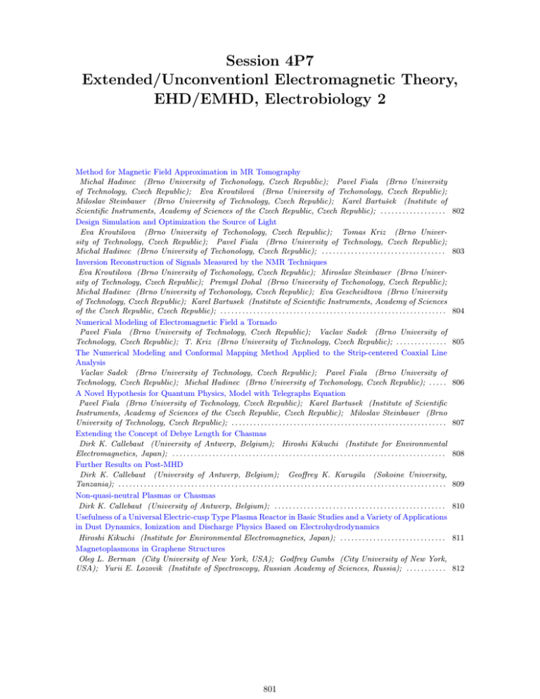
Session 4P7 Extended/Unconventionl Electromagnetic Theory, EHD/EMHD, Electrobiology 2 Method for Magnetic Field Approximation in MR Tomography Michal Hadinec (Brno University of Techonology, Czech Republic); Pavel Fiala (Brno University of Technology, Czech Republic); Eva Kroutilová (Brno University of Techonology, Czech Republic); Miloslav Steinbauer (Brno University of Technology, Czech Republic); Karel Bartušek (Institute of Scientific Instruments, Academy of Sciences of the Czech Republic, Czech Republic); . . . . . . . . . . . . . . . . . . Design Simulation and Optimization the Source of Light Eva Kroutilova (Brno University of Techonology, Czech Republic); Tomas Kriz (Brno University of Technology, Czech Republic); Pavel Fiala (Brno University of Technology, Czech Republic); Michal Hadinec (Brno University of Techonology, Czech Republic); . . . . . . . . . . . . . . . . . . . . . . . . . . . . . . . . . . Inversion Reconstruction of Signals Measured by the NMR Techniques Eva Kroutilova (Brno University of Techonology, Czech Republic); Miroslav Steinbauer (Brno University of Technology, Czech Republic); Premysl Dohal (Brno University of Techonology, Czech Republic); Michal Hadinec (Brno University of Techonology, Czech Republic); Eva Gescheidtova (Brno University of Technology, Czech Republic); Karel Bartusek (Institute of Scientific Instruments, Academy of Sciences of the Czech Republic, Czech Republic); . . . . . . . . . . . . . . . . . . . . . . . . . . . . . . . . . . . . . . . . . . . . . . . . . . . . . . . . . . . . . . Numerical Modeling of Electromagnetic Field a Tornado Pavel Fiala (Brno University of Technology, Czech Republic); Vaclav Sadek (Brno University of Technology, Czech Republic); T. Kriz (Brno University of Technology, Czech Republic); . . . . . . . . . . . . . . The Numerical Modeling and Conformal Mapping Method Applied to the Strip-centered Coaxial Line Analysis Vaclav Sadek (Brno University of Technology, Czech Republic); Pavel Fiala (Brno University of Technology, Czech Republic); Michal Hadinec (Brno University of Techonology, Czech Republic); . . . . . A Novel Hypothesis for Quantum Physics, Model with Telegraphs Equation Pavel Fiala (Brno University of Technology, Czech Republic); Karel Bartusek (Institute of Scientific Instruments, Academy of Sciences of the Czech Republic, Czech Republic); Miloslav Steinbauer (Brno University of Technology, Czech Republic); . . . . . . . . . . . . . . . . . . . . . . . . . . . . . . . . . . . . . . . . . . . . . . . . . . . . . . . . . . . Extending the Concept of Debye Length for Chasmas Dirk K. Callebaut (University of Antwerp, Belgium); Hiroshi Kikuchi (Institute for Environmental Electromagnetics, Japan); . . . . . . . . . . . . . . . . . . . . . . . . . . . . . . . . . . . . . . . . . . . . . . . . . . . . . . . . . . . . . . . . . . . . . . . . . . . Further Results on Post-MHD Dirk K. Callebaut (University of Antwerp, Belgium); Geoffrey K. Karugila (Sokoine University, Tanzania); . . . . . . . . . . . . . . . . . . . . . . . . . . . . . . . . . . . . . . . . . . . . . . . . . . . . . . . . . . . . . . . . . . . . . . . . . . . . . . . . . . . . . . . . . . Non-quasi-neutral Plasmas or Chasmas Dirk K. Callebaut (University of Antwerp, Belgium); . . . . . . . . . . . . . . . . . . . . . . . . . . . . . . . . . . . . . . . . . . . . . . . Usefulness of a Universal Electric-cusp Type Plasma Reactor in Basic Studies and a Variety of Applications in Dust Dynamics, Ionization and Discharge Physics Based on Electrohydrodynamics Hiroshi Kikuchi (Institute for Environmental Electromagnetics, Japan); . . . . . . . . . . . . . . . . . . . . . . . . . . . . . Magnetoplasmons in Graphene Structures Oleg L. Berman (City University of New York, USA); Godfrey Gumbs (City University of New York, USA); Yurii E. Lozovik (Institute of Spectroscopy, Russian Academy of Sciences, Russia); . . . . . . . . . . . 801 802 803 804 805 806 807 808 809 810 811 812 802 Progress In Electromagnetics Research Symposium Abstracts, Hangzhou, China, March 24-28, 2008 Method for Magnetic Field Approximation in MR Tomography Michal Hadinec1 , Pavel Fiala1 , Eva Kroutilová1 Miroslav Steinbauer1 , and Karel Bartušek2 1 Institute of Scientific Instruments of the ASCR, v.v.i Královopolská 147, 612 64, Brno, Czech Republic 2 Department of Theoretical and Experimental Electrical Engineering Faculty of Electrical Engineering and Communication, Brno University of Technology Kolejnı́ 2906/4, 612 00, Brno, Czech Republic Abstract— This paper describes a method, which can be used for creating map of magnetic field. Method has a great usage in magnetic resonance tomography, when we need to get information about homogeneity and characteristics of magnetic field inside the working space of the MR tomograph. The main purpose of this article is to describe basic principles of magnetic resonance phenomenon and mathematical method of Legendre polynoms which can be used for signal processing of FID (Free Induction Decay) signal obtained from tomograph detection coils. In the end of my article is experimental solution of magnetic field and models of magnetic field created by Matlab. Introduce Magnetic resonance tomography is an imaging technique used primary in medical setting to produce high quality images of the human body. Magnetic resonance imaging is based on the principles of nuclear magnetic resonance (NMR) and at the present time it is the most developed imaging technique at biomedical imaging [2]. Lately, medical science lays stress on the measuring of exactly defined parts of human body, especially human brain. If we want to obtain the best quality images we have to pay attention to homogeneity of magnetic fields, which are used to scan desired samples inside the tomograph. We should know how to reduce inhomogeneity, which can cause misleading information at the final images of samples. Generally, inhomogeneity of magnetic fields at magnetic resonance imaging cause contour distortion of images. To eliminate these inhomogeneity correctly, we need to know the map of the magnetic field and we also need to have an exact information about parameters of the magnetic field. This paper presents the experimental method, which can easily create the map of electromagnetic induction at any defined area inside the tomograph. This method uses mathematical theory of Legendre polynoms, which are used for approximation of magnetic field, if we know specific coefficients. The coefficients of Legendre polynoms, which are computed using measured values of magnetic induction at exactly defined discrete points are used for creating map of magnetic field. If we know these coefficients, we are able to compute magnetic induction at any point of defined area. At the ideal case, there should be no difference between measured data and approximated data. REFERENCES 1. Fiala, P., E. Kroutilová, and T. Bachorec, Modelovánı́ elektromagnetickhých polı́, počı́tačová cvičenı́ vyd. Brno: VUT v Brně, FEKT, Údolnı́ 53, 602 00, Brno, 2005. 2. Haacke, E. M., R. W. Brown, M. R. Thomson, and R. Venkatesan, Magnetic resonance imagingphysical principles and sequence design, John Wiley & Sons, ISBN 0-471-48921-2, 2001. 3. Stratton, J. A., Teorie elektromagnetického pole, SNTL Praha, 1961. 4. Angot, A., Užitá matematika, Státnı́ nakladatelstvı́ technické literatury, Praha 1972. 5. Morris, P. G., Nuclear Magnetic Resonance Imaging in Medicine and Biology, Clearendon Press, Oxford, 1986. Progress In Electromagnetics Research Symposium Abstracts, Hangzhou, China, March 24-28, 2008 803 Design Simulation and Optimization the Source of Light Eva Kroutilová, Tomáš Křı́ž, Pavel Fiala, and Michal Hadinec Department of Theoretical and Experimental Electrical Engineering, Brno University of Technology Kolejni 4, 612 00 Brno, Czech Republic Abstract— This paper presents information about design of light sources, which is intended for commercial use. Required properties were continuous spectral characteristic with respect to active wavelength area, 3D light characteristics. Design of light source consisting of classical used light source, as well as experimental results, are presented. The light source was designed, optimized and tested for the research activity. REFERENCES 1. 2. 3. 4. 5. 6. 7. 8. 9. GM Electronic, Katalog elektronických součástek, 2005. Světlo, ISSN 1212-0812, FCC Public s.r.o., Pod Vodárenskou věžı́ 4, 182 08, Praha 8, ČR. Plch, J., J. Mohelnı́ková, and P. Suchánk, Osvětlenı́ neosvětlitelných prostor, ERA, 2004. LEOS Newsletter Magazine, Lasers and Electro-Optics Society of the Institute of Electrical and Electronics Engineers, Inc., Corporate Office: 3 Park Ave., 17th Floor, New York, NY 10016-5997, USA. Plch, J., Světelná technika v praxi, IN-EL 1999, Praha, 210 stran, ISBN 80-86230-09-0. Habel, J. a. K, Světelná technika a osvětlovánı́, FCC Public, Praha, 448 stran, ISBN 800901985-0-3, 1995. Govindjee, Bioenergetics of Photosynthesis, Academic Press, New York, 1975. Campbell, N. and J. Reece, Benjamin Cummings., Biology 7th ed., San Francisco, 2005. http://www.esim.ca/2002/documents/Proceedings/other2.pdf. 804 Progress In Electromagnetics Research Symposium Abstracts, Hangzhou, China, March 24-28, 2008 Inversion Reconstruction of Signals Measured by the NMR Techniques Eva Kroutilova1 , Miloslav Steinbauer1 , Premysl Dohal1 Michal Hadinec1 , Eva Gescheidtova1 , and Karel Bartušek2 1 2 Brno University of Technology, Czech Republic Academy of Science of the Czech Republic, Czech Republic Abstract— The paper describes the magnetic resonance imaging method applicable mainly in MRI and MRS in vivo studies. We solved the effect of changes of magnetic fields in MR tomography. This article deals with the reverse reconstruction results obtained from the numerical simulation of MR signals by various techniques, which will be usable for the experimental results verification. Geometrical Model: Figure 1 describes the sample geometry for the numerical modeling. On both sides, the sample is surrounded by the referential medium. During the real experiment, the reference is represented by water, which is ideal for obtaining the MR signal. Figure 1: The sample geometry for numerical modeling. Figure 2: The geometrical model in the system Ansys. REFERENCES 1. Fiala, P., E. Kroutilová, and T. Bachorec, Modelovánı́ elektromagnetických polı́, počı́tačová cvičenı́, vyd, VUT v Brně, Brno, FEKT, Údolnı́ 53, s. 1–69, 602 00, Brno, 2005. 2. Steinbauer, M., Měřenı́ magnetické susceptibility technikami tomografie magnetické rezonance, vyd, VUT v Brně, Brno, FEKT, Údolnı́ 53, 602 00, Brno, 2006. Progress In Electromagnetics Research Symposium Abstracts, Hangzhou, China, March 24-28, 2008 805 Numerical Modeling of Electromagnetic Field a Tornado P. Fiala, V. Sadek, and T. Kriz Department of Theoretical and Experimental Electrical Engineering Brno University of Technology, Kolejni 2906/4, 612 00 Brno, Czech Republic Abstract— This article deals the numerical model with physical and chemical processes in the tornado. There are presented basic theoretical model and numerical solution. We prepared numerical models based on combined finite element method (FEM) and finite volume method (FVM). The model joins magnetic, electric and current field, flow field and chemical nonlinear ion model. Results were obtained by means of FEM/FVM as a main application in ANSYS software. Introduction: The full electro-hydro-dynamical (EHD) model of inductive tornado is coupled problem. There are coupled electric, magnetic, fluid flow field and electric circuit and chemical (ions) models. This model was solved with combined finite element methods (FEM) and finite volume methods (FVM). Results from numerical model were tested. REFERENCES 1. Fala, P., “Model of inductive flowmeter DN-100,” Research report No. 2/01, 1–23, Laboratory of modelling and optimisation of electromechanical systems BUT FECT, Brno, Czech Republic, June 21, 2001, 2. Fleischner, P., Hydromechanika, Paperback VUT FS, VUT Brno, ISBN 80-214-0266-1, 1990. 3. Černoch, S., Strojně technická přı́ručka, SNTL Praha, 1968. 4. Moore, J. W., Fyzikálnı́ chemie, SNTL Praha, 1981. 5. Brdička, R. and J. Dvořák, Základy fyzikálnı́ chemie, Academia Praha, 1977. 806 Progress In Electromagnetics Research Symposium Abstracts, Hangzhou, China, March 24-28, 2008 The Numerical Modeling and Conformal Mapping Method Applied to the Strip-centered Coaxial Line Analysis V. Šádek, P. Fiala, and M. Hadinec Faculty of Electrical Engineering and Communication, Brno University of Technology Kolejni 2906/4, Brno 612 00, Czech Republic Abstract— The boundary element method (BEM) is used for the strip centered coaxial line (SCCL). The common microstrip line has one disadvantage √ — a lot of electromagnetic field is spread outside the dielectric substrate. This field moves er times faster than field under the microstrip inside the dielectric substrate. This deformation of the field (HEM wave) complicates the application of the microstrip line on frequencies over c. 20 GHz. Described complication can be eliminated in the structure, which cumulates major portmon of power density of the EM field in dielectric substrate to the detriment of free space above the strip. Introduction: A lot of different electronic equipments have to work together. Unfortunately the power levels among them are over 200 dB very often. Coaxial structures are widely used because of their good shielding effect, which suppress the fields around strong distortion sources (e.g., transmitting antenna feeder) and protect sensitive parts of receivers, measurements etc. [1, 2]. Whereas coaxial line (two concentric cylindrical electrodes) is widely known, strip-centered coaxial line (SCCL, Fig. 1.) is mentioned rarely (founded only in very special literature like [3]).The SCCL structure also offers a very attractive occasion of matching to microstrip line, coplanar waveguide, etc. REFERENCES 1. Svačina, J., Electromagnetic Compatibility — Lectures, Textbook of Brno University of Technology, FEKT VUT Brno, 2002. 2. Armstrong, K., Design Techniques for EMC, http://www.complianceclub.com/keith armstrong.asp. 3. Wadell, B. C., Transmission Line Design Handbook, Artech House, Boston/London, 1991. 4. Driscoll, T. A., SC-Toolbox, for MATLAB, http://www.math.edu/ driscoll/SC/. 5. Paris, F. and J. Canas, Boundary Element Method, Oxford University Press, Oxford, 1997. 6. Bongianni, W. L., “Fabrication and performance of strip-centered microminiature coaxial cable,” Proceeding of the IEEE, Vol. 72, No. 12, 1810–1811, December 1984. 7. Hilberg, W., Electric Characteristics of Transmission Lines, 122, Artech House Nooks, Dedham, MA, 1979. Progress In Electromagnetics Research Symposium Abstracts, Hangzhou, China, March 24-28, 2008 807 A Novel Hypothesis for Quantum Physics, Model with Telegraphs Equation P. Fiala1 , K. Bartusek2 , and M. Steinbauer1 1 Department of Theoretical and Experimental Electrical Engineering University of Technology Brno, Kolejni 4, 612 00 Brno, Czech Republic 2 Institute of Scientific Instruments, Academy of Sciences of the Czech Republic Královopolská 147, 612 64 Brno, Czech Republic Abstract— The article describes a test of numerical model of the electron beam according to present knowledge of references [1–5]. The basic configuration of the electron beam was verified in Institute of Scientific Instruments Academy of Sciences of the Czech Republic experimentally. We prepared the numerical model which is based on the particle theory. Actually, it respects classical Electrodynamics Material Wave Theory (MWT). Numerical results were evaluated. The second model was prepared in respect to theory of wave packet (Louis de Broglie) and solved again. Results of both models were the same in their quality, we evaluated electric field intensity E on the electron impact area, and they corresponded with results from experiments. REFERENCES 1. Van Vlaenderen, K. J. and A. Waser, “Electrodynamics with the scalar field,” Physics, Vol. 2, 1–13, 2001. 2. Kikuchir, H., “Electrohydrodynamics in dusty and dirty plasmas, gravito-electrodynamics and EHD,” Kluwer academic publishers, Dordrecht/Boston/London, 2001. 3. Van Vlaenderen, K. J., “A charge space as the orogin of sources, fields and potentials,” Physics, arXiv: physics/9910022 v1, 1–13, 16 Oct., 1999. 4. Hofer, W. A., “A charge space as the origin of sources, fields and potentials,” Physics, arXiv: quant-ph/ 9611009 v3, 1–13, 17 Apr., 1997. 5. Prosser, V a K., “Experimentálnı́ metody biofyziky,” Academia, Praha, 1989. 6. Delong, A., “Verbal information,” Czech Academy of Science, ISI Brno, Brno, 7. 2. 2006. 7. Bartusek, K. and P. Fiala, “A simple numerical simulation of internal structure of particles test,” PIERS 2007, Beijing, China, March 2007. 808 Progress In Electromagnetics Research Symposium Abstracts, Hangzhou, China, March 24-28, 2008 Extending the Concept of Debye Length for Chasmas D. K. Callebaut1 and H. Kikuchi2 1 Physics Dept., CDE, University of Antwerp, Antwerp, B-2610, Belgium 2 Institute for Environmental Electromagnetics, Tokyo 170, Japan Abstract— Chasmas are a generalization of plasmas, i.e., the condition of quasi-neutrality is dropped. That means that in chasmas the quasi-neutrality may be (strongly) violated over distances many times the Debye length which requires special circumstances (double layers, electric fields, . . .). The question arises what the meaning is of a shielding length in chasmas. It was demonstrated that the so-called chasma (angular) frequency has an expression similar to the plasma frequency: |n− − n+ |e2 ωc2 = , εm− with an obvious notation. However, this chasma frequency plays a role as well in the equilibrium (or steady state) as in the stability. For the ‘Debye length in chasmas’ we obtained λ2c = εkB T , (n+ + n− )e2 supposing the temperature of electrons and ions is the same, that the ions are only once ionized and that kT À eϕ (kinetic energy much larger than potential energy). This means that the chasma shielding length is much the same as the Debye length and that λc ωp ∼ λD ωp ∼ kB T while λc ωc make a rather different combination involving the temperature and the degree of non-quasi-neutrality n− − n+ . n− + n+ However, some comments are in place. First the equilibrium has the same structure, so that the general shape of the chasma and the shape near the extra charge introduced in it have a different amplitude, but the same shape. (Cf. the same situation for ωc which plays a role in the equilibrium and in the perturbation.) Second, the question of the universality of the expression for λc arises, although we obtained it for two cases (one equilibrium and one steady state). Indeed, chasmas require extra forces or conditions to exist and each case needs a somewhat adapted treatment. However, on general grounds we expect the expression rather general. REFERENCES 1. Callebaut, D. K., G. K. Karugila, and A. H. Khater, “Chasma perturbations,” Proc. PIERS 2005, 720–723, Hangzhou, China, August 22–26, 2005. 2. Callebaut, D. K. and A. H. Khater, “Chasma including magnetic effects,” Proc. PIERS 2006, 404–411, Cambridge, USA, March 26–29, 2006. 3. Callebaut, D. K. and H. Kikuchi, “Debye shielding in chasmas,” Proc. PIERS 2007, Prague, 27–30 August, 2007. Progress In Electromagnetics Research Symposium Abstracts, Hangzhou, China, March 24-28, 2008 809 Further Results on Post-MHD D. K. Callebaut1 and G. K. Karugila2 1 Physics Department, CDE, University of Antwerp, Antwerp, B-2610, Belgium 2 Sokoine University, Morogoro 3038, Tanzania Abstract— This paper continues the previous work on post-magnetohydrodynamics [3]. In magnetohydrodynamics (MHD) Maxwell’s displacement current is neglected. From the evolution equation for MHD (either ideal or not) one obtains the magnetic field and through Maxwell’s equations one may calculate the electric field, the current and the electric charge. This allows to verify the neglect of the displacement term. The exact solution obtained by Callebaut for ideal MHD allows a rigorous calculation (for a given velocity profile and a given initial field) of the neglected term. The displacement current yields a correction term which may require an iteration. This corresponds to pass from MHD to Post-MHD. In Ref. 3 it was shown that the displacement current exceeds the MHD current when the time derivative divided by c2 exceeds the second order space derivatives multiplied by the time lapse in the case treated. Further examples are given. It results that precisely at the start of a magnetic phenomenon the displacement current may play a role: this is related to Lenz law. For longer times the displacement current fades out. As a side result the question of quasi-neutrality is considered (cf. the concept of non-quasi-neutral plasmas or “chasmas”). REFERENCES 1. Callebaut, D. K. and V. I. Makarov, “Generation of sunspots and polar faculae from a kinematic dynamo,” Proc. IX Pulkovo International Conference on Solar Physics: Solar Activity as a factor of Cosmic Weather, (Pulkovo) Main Astronomical Observatory, 4–9 July 2005 (A. V. Stepanov, A. A. Solov’ev & V. A. Dergachev, directors), (Mostly in Russian), 196140 St. Petersburg, Russia, 379–388, 2005. 2. Callebaut, D. K. and A. H. Khater, “Generation of sunspot and polar faculae butterflies using bipolar and quadripolar seed field,” Proc. IAU Symposium 233, Solar Activity and Its Magnetic Origin, 9–16, Eds. V. Bothmer and A. A. Hady, Cairo, Egypt, March 31–April 4, 2006. 3. Callebaut, D. K. and A. H. Khater, “Post-Magnetohydrodynamics,” PIERS07, 989–993, (+ CD-Rom), Beijing, China, March 26–30, 2006. 810 Progress In Electromagnetics Research Symposium Abstracts, Hangzhou, China, March 24-28, 2008 Non-quasi-neutral Plasmas or Chasmas D. K. Callebaut Physics Department, CGB, University of Antwerp, Antwerp, B-2020, Belgium Abstract— By definition a plasma is quasi-neutral over distances of the order of the Debye length. However, there are many cases in which there is no quasi-neutrality over distances of many Debye lengths. Such a “charged plasma” has been called plasma. Several types of this may occur in the cavities of particle accelerators or in (re-entrant) cavities according to the sign of the ionizing beam (+, 0 or −), its orientation, the residual gas pressure, the geometry and the presence of a magnetic field (parallel or perpendicular). This may be studied using a (partial) integro-differential equation or more geneneral, using the Maxwell equations from the start in 1D, 2D or 3D. We define the chasma frequency, similar to the plasma frequency, but playing a role in the equilibrium or steady state as well as in the stability analysis. The extension of the Debye length and potential is considered. Other cases of chasmas are briefly considered (chasma surrounded by isolating walls, double layers, double current layers, pure electron gas in crossed magnetic field and rotation, It may be noted that plasma instabilities often show non-quasineutrality which may lead to wrong results if the corresponding frequencies are used instead of the ones for chasmas. Clearly a cavity filled with a chasma has a different resonance frequency then when empty. Progress In Electromagnetics Research Symposium Abstracts, Hangzhou, China, March 24-28, 2008 811 Usefulness of a Universal Electric-cusp Type Plasma Reactor in Basic Studies and a Variety of Applications in Dust Dynamics, Ionization and Discharge Physics Based on Electrohydrodynamics H. Kikuchi Institute for Environmental Electromagnetics, 3-8-18, Komagome, Toshima-ku, Tokyo 170, Japan Abstract— A universal electriac-cusp type plasma reactor designed more than a decades ago by the present author has successfully been in operation for the last coupe of years and has been proved useful for basic studies and a variety of applications in dust dynamics, ionization and discharge physics, including laboratory simulation of universe, atmospheric and space electricity and plasmas, based on ‘Electrohydrodynamics (EHD)/Electromagnetohydrodynamics (EMHD). This paper aims to present the structure and operation of this plasma reactor and to show how this device is useful for basic studies and applications, citing a number of examples. The new device is a square box with two lead electrodes (15 mm in diameter and 5 cm in interval) inside, suspended 2.75 ∼ 5 cm above a metallic plate. When a tiny object or dust grain, conducting or dielectric, is placed in the cusp center, electric field line merging toward it occurs from the four or two poles, inducing or polarizing electric charges on its surface or in its volume, negative or positive facing positive or negative poles, respectively. Then a catastrophe occurs, namely zero-electric field without the object or dust suddenly tends to sufficiently high electric fields, almost infinity, around it. We are now ready to be advanced to one of entirely different two directions, depending upon the background gas pressure. One is the case of energy transfer from fields to kinetic energy leading to dust dynamics in a pair of electric mirror for the background gas pressure below the breakdown threshold, and the other is the case of energy transfer from fields to ionization resulting in an electric discharge for the background gas pressure beyond the breakdown threshold. First we deal with the former case. When an uncharged dust grain, conducting or dielectric, is placed onto the center of a quadrupole, dust starts moving between conjugating mirror points and is going back and forth undulating the mid-plane. If a dust grain is negatively or positively charged its motion in periodic cusps and mirrors in the midplane of a quadrupole forming an electric mirror. Next we proceed to three dimensional motion of an uncharged or charged dust grain not in the ecliptic plane of a quadrupole, Then the dust grain is going to helical motion due to helicity generation of an electric quadrupole. The second case when the background gas pressure is beyond the breakdown threshold leads to a variety of electric discharge phenomena, laboratory evidence of ’electric cusp-mirror and reconnection model’ as well as the first case and provides basic studies of ionization and dischatge processes, laboratory simulations of universe, atmospheric and space electric electricity and plasma phenomena, applications to industrial plasmas, including plasma processing, new material production such as diamond, electric precipitator and so on. Progress In Electromagnetics Research Symposium Abstracts, Hangzhou, China, March 24-28, 2008 812 Magnetoplasmons in Graphene Structures Oleg L. Berman1 , Godfrey Gumbs2 , and Yurii E. Lozovik3 1 Physics Department, New York City College of Technology, City University of New York, USA 2 Department of Physics, Hunter College, City University of New York, USA 3 Institute of Spectroscopy, Russian Academy of Sciences, Russia Abstract— Recent progress in technology has allowed the production of graphene, which is a two-dimensional honeycomb lattice of carbon atoms that form the basic planar structure in graphite. [1, 2] Graphene has attracted strong theoretical attention as a gapless semiconductor with an unusual massless Dirac-fermion band structure. The unusual many-body interactions in graphene have been investigated. [5] The integer quantum Hall effect (IQHE) has been discovered in graphene in recent experiments. [6–8] The quantum Hall ferromagnetism in graphene has been studied theoretically. [9] The spectrum of plasmon excitations in a single graphene layer immersed in a material with effective dielectric constant εs without magnetic field (B = 0) was calculated in Ref. [10]. We calculated the spectrum of magnetoplasmon excitations in graphene layer immersed in a dielectric in strong magnetic fields B = 5T and B = 10T applying the random phase approximation (RPA). Besides, we have calculated the spectrum of magnetplasmon excitations in graphene bilayer and an infinite superlattice of graphene layers immersed in a dielectric. We analyze the dispersion relation in detail. Our numerical calculations reveal symmetric and antisymmetric plasmon modes for bilayer graphene as well as a negative group velocity for a range of wave vectors. There is Landau damping of the plasmon excitations by the particle-hole modes in some regimes of the wavelength of the collective plasmon branches. Our formalism is valid for arbitrary filling factor and temperature. Plasma instabilities associated with these layered structures will be explored as a source of electro-magnetic radiation. REFERENCES 1. 2. 3. 4. 5. 6. 7. 8. 9. 10. Novoselov, K. S., et al., Science, Vol. 306, 666, 2004. Zhang, Y., et al., Phys. Rev. Lett., Vol. 94, 176803, 2005. DiVincenzo, D. P. and E. J. Mele, Phys. Rev. B, Vol. 29, 1685, 1984. Kane, C. L. and E. J. Mele, Phys. Rev. Lett., Vol. 78, 1932, 1997. Sarma, S. D., E. H. Hwang, and W.- K. Tse, Phys. Rev. B, Vol. 75, 121406(R), 2007. Novoselov, K. S., et al., Nature, Vol. 438, 197, London, 2005. Zhang, Y. B., et al., Nature, Vol. 438, 201, London, 2005. Zhang, Y., et al., Phys. Rev. Lett., Vol. 96, 136806, 2006. Nomura, K. and A. H. MacDonald, Phys. Rev. Lett., Vol. 96, 256602, 2006. Sarma, S. D. and E. H. Hwang, Phys. Rev. Lett., Vol. 81, 4216, 1998.
