Instruction Sheet
SMA Bulkhead Feedthrough Cable Jacks
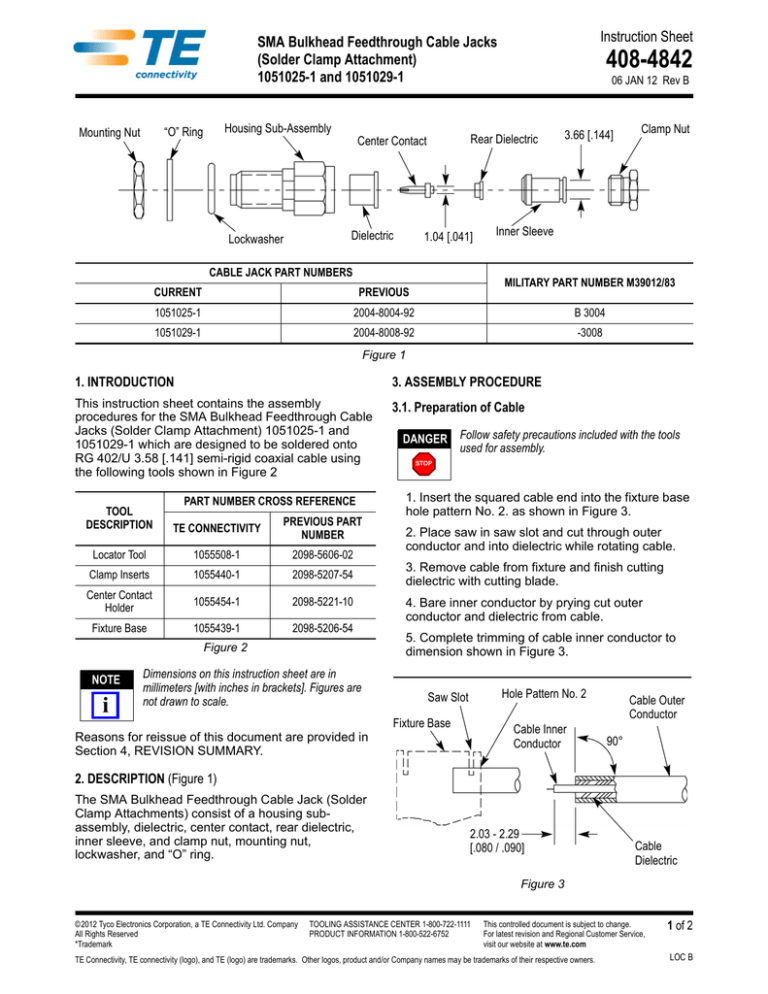
(Solder Clamp Attachment)
1051025-1 and 1051029-1
Housing Sub-Assembly
“O” Ring
Mounting Nut
06 JAN 12 Rev B
Rear Dielectric
Center Contact
Dielectric
Lockwasher
408-4842
1.04 [.041]
CABLE JACK PART NUMBERS
3.66 [.144]
Clamp Nut
Inner Sleeve
MILITARY PART NUMBER M39012/83
CURRENT
PREVIOUS
1051025-1
2004-8004-92
B 3004
1051029-1
2004-8008-92
-3008
Figure 1
1. INTRODUCTION
3. ASSEMBLY PROCEDURE
This instruction sheet contains the assembly
procedures for the SMA Bulkhead Feedthrough Cable
Jacks (Solder Clamp Attachment) 1051025-1 and
1051029-1 which are designed to be soldered onto
RG 402/U 3.58 [.141] semi-rigid coaxial cable using
the following tools shown in Figure 2
3.1. Preparation of Cable
PART NUMBER CROSS REFERENCE
DANGER Follow safety precautions included with the tools
used for assembly.
STOP
1. Insert the squared cable end into the fixture base
hole pattern No. 2. as shown in Figure 3.
TOOL
DESCRIPTION
TE CONNECTIVITY
PREVIOUS PART
NUMBER
Locator Tool
1055508-1
2098-5606-02
Clamp Inserts
1055440-1
2098-5207-54
Center Contact
Holder
3. Remove cable from fixture and finish cutting
dielectric with cutting blade.
1055454-1
2098-5221-10
Fixture Base
1055439-1
2098-5206-54
4. Bare inner conductor by prying cut outer
conductor and dielectric from cable.
Figure 2
NOTE
i
Dimensions on this instruction sheet are in
millimeters [with inches in brackets]. Figures are
not drawn to scale.
2. Place saw in saw slot and cut through outer
conductor and into dielectric while rotating cable.
5. Complete trimming of cable inner conductor to
dimension shown in Figure 3.
Hole Pattern No. 2
Saw Slot
Fixture Base
Cable Inner
Conductor
Reasons for reissue of this document are provided in
Section 4, REVISION SUMMARY.
Cable Outer
Conductor
90°
2. DESCRIPTION (Figure 1)
The SMA Bulkhead Feedthrough Cable Jack (Solder
Clamp Attachments) consist of a housing subassembly, dielectric, center contact, rear dielectric,
inner sleeve, and clamp nut, mounting nut,
lockwasher, and “O” ring.
2.03 - 2.29
[.080 / .090]
Cable
Dielectric
Figure 3
© 2012 Tyco Electronics Corporation, a TE Connectivity Ltd. Company
All Rights Reserved
*Trademark
TOOLING ASSISTANCE CENTER 1-800-722-1111
PRODUCT INFORMATION 1-800-522-6752
This controlled document is subject to change.
For latest revision and Regional Customer Service,
visit our website at www.te.com
TE Connectivity, TE connectivity (logo), and TE (logo) are trademarks. Other logos, product and/or Company names may be trademarks of their respective owners.
1 of 2
LOC B
408-4842
3.2. Soldering of Inner Sleeve to Cable
Rear Dielectric
1. Place clamp nut and inner sleeve on end
of cable.
Solder Sleeve
Heat Here
2. Place loose assembly in fixture base as shown in
Figure 4. (Slide clamp nut back out of way).
3. Nest cable in locator tool.
4. Tighten clamp screw to secure cable.
Center Contact
5. Tighten locator tool to seat cable firmly.
Center Contact Holder
6. Slide inner sleeve against locator tool.
7. Maintain position of inner sleeve firmly against
locator tool and solder.
NOTE
Fixture vase should be clamped vertically in vise to
keep inner sleeve seated against locator tool.
i
Clamp
Screw
Fixture Base
Clamp Insert
Solder Here
60/40
Figure 5
3.4. Secure Inner Sleeve Sub-Assembly to Housing
1. Assemble front dielectric onto center contact as
shown in Figure 6.
2. Slide clamp nut over inner sleeve and
engage threads of clamp to housing. Torque
to 2.83-3.39 N•m [25-30 in-lb].
3. Assembly is now complete.
Housing
Front Dielectric
Center Contact
Locator Tool
(Optional)
Cable Sub-Assembly
Clamp Assembly
Figure 6
Figure 4
3.3. Soldering of Center Contact to Cable Inner
Conductor
1. Tin inner conductor of cable.
2. Place rear dielectric onto cable inner conductor
as shown in Figure 5.
3. Place center contact in holder. Heat center
contact and push it over inner conductor of cable
with the large diameter of contact resting firmly
against rear dielectric.
CAUTION Damaged components may not be used. They
must be replaced with new components.
!
4. REVISION SUMMARY
Since the previous version of this document, the
following changes were made:
• Updated document to corporate requirements.
4. Remove excess solder.
Rev B
2 of 2


