D. Electrical Networks
advertisement

I ntroduction
13
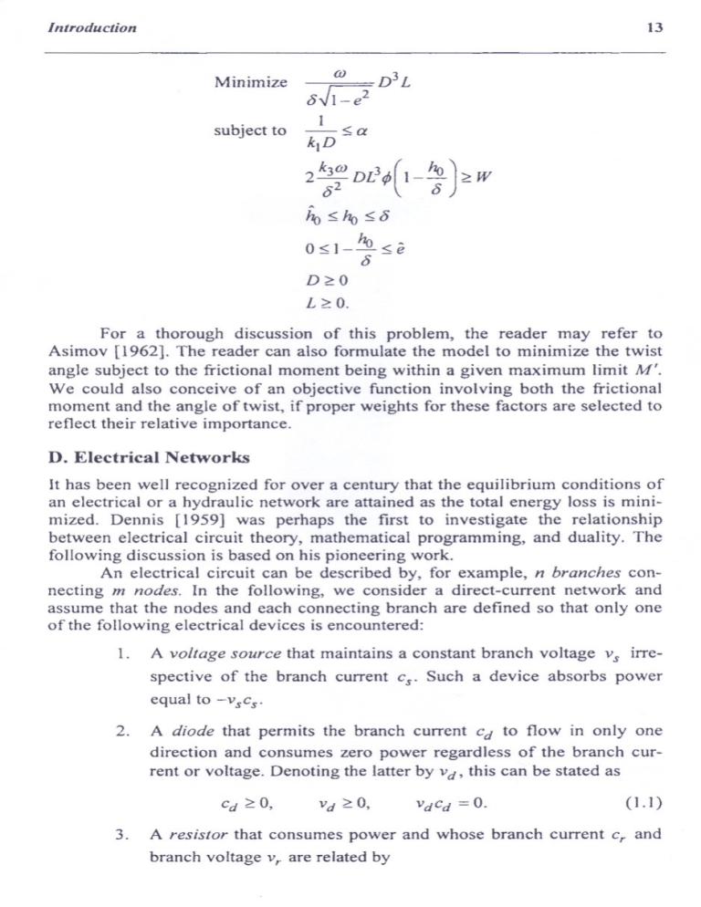
Minimize
D3 L
úJ
o~
--5: a
1
subjeet to
klD
02 DL3t/J(1- 170
O J ~ W
2 k3úJ
1705:1705:0
05:]-
1705:ê
O
D
C. O
L ~O.
For a thorough discussion of this probJem, the reader may refer to
Asimov [1962]. The reader can aIso formulate the modeI to minimize the twist
angle subject to the frictional moment being within a given maximum limit M'.
We could also eonceive of an objeetive funetion involving both the frietional
moment and the angle of twist, if proper weights for these faetors are seleeted to
refleet their relative importance.
D. Electrical Networks
It has been weIl recognized for over a century that the equilibrium eonditions of
an e]eetrical or a hydraulic network are attained as the total energy 10ss is minimized. Dennis [1959] was perhaps the first to investigate the relationship
between eleetrical cireuit theory, mathematieal programming, and duality. The
foIlowing diseussion is based on his pioneering work.
An eleetrical circuit ean be described by, for example, n branches conneeting m nodes. In the following, we eonsider a direet-eurrent network and
assume that the nodes and eaeh conneeting braneh are defined so that only one
ofthe following electricaI devices is encountered:
1.
A voltage source that maintains a constant branch voltage Vs irrespeetive of the branch current
cS'
Sueh a device absorbs power
equal to -vscs'
2.
A diode that permits the braneh current cd to flow in only one
direction and consumes zero power regardless of the branch current or voltage. Denoting the Jatter by vd' this can be stated as
(1. ])
3.
A resistor that consumes power and whose branch current cr and
braneh voltage vr are related by
14
Chapter 1
( 1.2)
where r is the resistance of the resistor. The power consurned
given by
is
( 1.3)
The three devices are shown schematical1y in Figure 1.5. The current
flow in the diagram is shown from the negative terminal of the branch to the
positive terminal of the branch. The former is calIed the origin node, and the
latter is the ending node ofthe branch. Ifthe current flows in the opposite direction, the corresponding branch current will have a negative value, which, inci·
dentally, is not perrnissible for the diode. The same sign convention will be used
for branch voltages.
A network having a number of branches can be described by a nodebranch incidence matrix N, whose rows correspond to the nodes and whose
columns correspond to the branches. A typical element nij of N is given by
i
j has node as its origin
if branch j ends in node i
if branch
nij
=
1
{-I
O
otherwise.
For a network having several voltage sources, diodes, and resistors,
let
Ns
denote the node-branch incidence matrix for alI the branches having voltage
sources, N D denote the node-branch incidence rnatrix for alI branches having
diodes, and N R denote the node-branch
incidence matrix for alI branches having
resistors. Then, without loss of generality, we can partition N as
Similarly, the column vector c, representing
tioned as
+
Vs
Figure 1.5 Typical electrical
the branch currents, can be parti-
+~o
o-Jwv--o
o---c>r---o
Resistor
::::::Cd
Vd
Cr
Vr Diode
devices in a circuito
lntroduction
15
and the column vector v, representing the branch voltages, can be written as
Associated with each node i is a node potential Pi' The column vector p,
representing
node potentiaIs, can be written as
The following
basic laws govem the equilibrium
conditions
of the net-
work:
Kircllhoff's node law. The sum of ali currents entering a node is equal to the
sum of ali currents leaving the node. This can be written as Nc
= O, or
(1.4)
KirchhoJf's loop law. The difference between the node potentials at the ends of
each branch is equal to the branch voltage. This can be written as Nt p ::::v, or
( 1.5)
In addition, we have the equations representing the characteristics
cal devices. From (1.1), for the set of diodes, we have
of the electri-
( 1.6)
and trom (1.2), for the resistors, we have
(1.7)
where R is a diagonaI matrix whose diagonaI elements are the resistance values.
Thus, (1.4) - (1.7) represent the equilibrium conditions ofthe circuit, and
we wish to find v D, v R' c, and p satisfying these conditions.
Now, consider the following quadratic programming problem, which is
discussed in Section 11.2:
1
t
t
Minimize
-cRRcR
2
subject to
Nscs+NDcD+NRcR
- v sCs
::::0
-cD ~ O.
16
Chapter 1
Here we wish to determine the branch currents cs, cD, and cR to minimize the
sum of half the energy absorbed in the resistors and the energy loss of the
voltage source. From Section 4.3 the optimality conditions for this problem are
N~u-vS=O
N~u-Iuo=O
N~u+RcR=O
Nscs +NDcD
= O
+NRcR
cbuo =
cD'uO
O
~ O,
the Lagrangian multip/iers. It
where u and uo are column vectors representing
can readily be verified that letting v D = uo, P = u, and noting (1.7), the conditions above are precisely the equilibrium conditions (1.4) - (1.7). Note that the
Lagrangian multiplier vector u is precisely the node potential vector p.
Associated with the above problem is another problem, referred to as the
dual problem (given below), where G = R-I is a diagonal matrix whose elements are the conductances
and where v S is fixed.
M
..
aXlmlze
1,
-2v R
G
vR
subject to N~p
= vS
N~p-VD
=
O
Nkp-VR
=
O
vD
Here, v~Gv
R
~ O.
is the power absorbed by the resistors, and we wish to find the
branch voltages v D and v R and the potential vector p.
The optimality conditions for this problem also are precise1y (1.4}-{1.7).
Furthermore, the Lagrangian multipliers for this problem are the branch currents.
It is interesting to note by Theorem 6.2.4, the main Lagrangian duality
theorem, that the objective function values of the above two problems are equal
at optimality; that is,
Since G = R -I and noting (1.6) and (1. 7), the above equation reduces to
which is precisely the principIe of energy conservation.
17
Jntroductioll
The reader may be interested in other applications of mathematical programming for solving problems associated with generation and distribution of
electrical power. A brief discussion, along with suitable references, is given in
the Notes and References section at the end of the chapter.
E. Water Resources Management
We now develop an optimization model for the conjunctive use of water
resources for both hydropower generation and agricultural use. Consider the
river basin depicted schematically in Figure 1.6.
A dam across the ri ver provides the surface water storage facility to provide water for power generation and agriculture. The power plant is assumed to
be dose to lhe dam, and water for agriculture is convcyed from the dam, directly
ar after power generation, through a canal.
There are two classes of variables associated with the problem:
1. Design variables: What should be the optimal capacity S of the
reservoir, the capacity U of the canal supplying agricultural
and the capacity E of the power plant?
2.
water,
Operational variables: How much water should be released for
agricultural power generation and for other purposes?
From Figure 1.6, the following operational variables can readily be identified for the jth period:
xJ
water released from the dam for agriculture
X)A =
waler released for power generation
use
~=====,
Figure 1.6 Typical river basin.
and then for agricultural
-_·-:-_---~-=--=--=-========I
Main canal
l
Agricu Itural
area


