™
Along with the wall box, the kit contains a stud
plate for attachment to a wall stud prior to drywall
installation.
5” and 7” In-Wall
Touch Screen Wall Box
Installation Guide
New Construction
Note: If the drywall is in place, use one of
the kits intended for retrofit (models C4RWB57C-P or C4-RWB57C-M).
Requirements
• Tools to install the wall box, such as a tape
measure, a pencil, a hammer or screwdriver
(depending on whether you are using screws
or nails), a drywall saw, a utility knife and other
common drywall tools.
• A 5/16” nut driver or socket wrench, if using the
metal wall box.
• Nails or screws (4 to 6).
What’s in the Kit
Supported Touch Screen Models
• C4-TSWMC5-EG-WH - 5” In-Wall Touch Screen,
White
• 5” and 7” In-Wall Touch Screen Wall Box for New
Construction
• Two (2) ferrite clamps with a rectangular
enclosure and one ferrite (1) clamp with a round
• C4-TSWMC5-EG-BL – 5” In-Wall Touch Screen,
Black
• C4-TSWMC7-EG-WH – 7” In-Wall Touch Screen,
enclosure
• 5” and 7” In-Wall Touch Screen Wall Box New
Construction Installation Guide (this document)
White
• C4-TSWMC7-EG-BL – 7” In-Wall Touch Screen,
Black
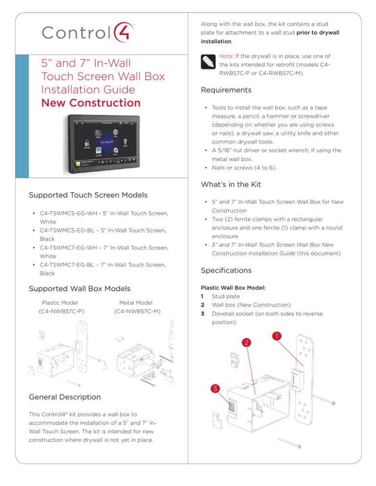
Supported Wall Box Models
Plastic Model
Metal Model
(C4-NWB57C-P)
(C4-NWB57C-M)
Specifications
Plastic Wall Box Model:
1
Stud plate
2
Wall box (New Construction)
3
Dovetail socket (on both sides to reverse
position)
2
General Description
This Control4® kit provides a wall box to
accommodate the installation of a 5” and 7” InWall Touch Screen. The kit is intended for new
construction where drywall is not yet in place.
3
1
™
New Device
5” and 7” In-Wall
Touch Screen Wall Box
Installation Guide
New Construction
AC Outlet
(unless using PoE)
• When using the Ethernet models near a location
where an Ethernet CAT5 cable is pulled.
• When using the wireless model above or near an
AC power source, such as an AC outlet.
Metal Wall Box Model:
1
Mounting location (on both sides to reverse
2
Hold the wall box and stud plate against the
position)
nearest stud, and mark the correct position
2
Wall box (New Construction)
according to your choices in Step 1. Follow these
3
Stud plate
guidelines.
3
a
Place the wall box so that, when mounted, it
will be flush with the surface of the drywall
2
after the drywall is installed. For example, if
1
the drywall is 3/8 of an inch deep, the front
rim of the wall box must be 3/8 of an inch
above the wall stud (toward you).
IMPORTANT! Make sure the wall box is flush
with the wall after the drywall is installed.
Allow 3/8 of an inch before the drywall is
installed (depending on the thickness of the
drywall), and err toward 5/16’s of an inch for
the best fit.
Installation
b
Install the wall box according to the arrows
inside the box that indicate the correct side
up.
Note: This kit is intended for installation of
a wall box prior to drywall installation. If the
drywall is already in place, use the retrofit
IMPORTANT! For safety reasons, install the
installation kit (C4-RWB57C-P or
wall box with the correct side up so the Touch
C4-RWB57C-M).
Screen interlocks with the wall box, allowing
Notes: (1) Install the wall box flush with the
a barrier to separate high-voltage from low-
wall. (2) Wall box dimensions: (H x W x D): 2.7”
voltage circuits.
x 4.1” x 2.4” (68mm x 104mm x 61mm).
1
c
either the right or the left side, depending
Find an appropriate wall box location for the
on which wall stud you choose. You may
Touch Screen you are installing:
detach the stud plate from the wall box on
• The wall box should be in a convenient location,
one side and reattach it on the opposite side
for example, near the entrance of a room.
if needed.
• The wall box should be at eye level,
approximately 57 to 61 inches from the floor.
Install the wall box with the stud plate on
3
Detach the stud plate from the wall box.
• Plastic box: Slide the wall plate toward the back
of the wall box.
rectangular enclosure and one ferrite (1) clamp with a
round enclosure.
• Metal box: Inscrew the wall box from the stud
plate.
Ferrite Clamp Installation when Using Power over
Ethernet (PoE)
This allows you to attach the stud plate to the wall
stud without interference from the wall box.
When powering the 5” or 7” In-Wall Touch Screen
using PoE, install the two (2) rectangular ferrite
4
Align the stud plate with the marks you made on
clamps on the Ethernet cable behind the wall box as
the stud (Step 2). If you are using a plastic unit,
shown next.
make sure the dovetail is toward the back of the
stud plate (away from you).
5
Nail or screw the stud plate to the wall stud.
6
Mount the wall box to the stud plate.
• Plastic box: Slide the wall box onto the stud
plate dovetail all the way, leaving the wall box
protruding the depth of the drywall, or slightly
less (Step 2a).
• Metal box: bolt the wall box back onto the stud
plate.
Note: If you are using a metal box, you can
Rectangular
Ferrite Clamps
continue to adjust its angle and position
slightly relative to the drywall.
7
Install the drywall according to the normal
procedures, making sure to cut the size of the
hole accurately.
8
After you install the drywall, carefully tighten the
screws to pull in the securing tabs so that the
wall box is flush with the surface of the wall.
Ferrite Clamp Installation when Using AC Power and
a WiFi Network Connection
When powering the Touch Screen using 110 or 240
VAC, install the round ferrite clamp on the AC cable
behind the wall box as shown below.
Note: Overtightening the screws may pull the
box into the wall.
IMPORTANT! When you are ready to install
the drywall, and you are cutting the opening
for the wall box, DO NOT cut the opening too
large. Be conservative and enlarge the hole as
needed, because there isn’t as much overhang
on the faceplate of the Touch Screen as you
are accustomed to using with standard switch
and outlet plates.
Ferrite Clamp Installation
When installing the Control4® 5” or 7” In-Wall Touch
Screen, also install the enclosed ferrite clamps (see
next figure) as described in this document. The wall
box packaging includes two (2) ferrite clamps with a
Round
Ferrite Clamp
Ferrite Clamp Installation when Using AC Power and
an Ethernet Network Connection
When powering the Touch Screen using AC and
connecting to the network using Ethernet, only install
one (1) rectangular ferrite clamp on the Ethernet
cable and one (1) round ferrite clamp on the AC cable
behind the wall box as shown next.
Rectangular
Ferrite Clamp
Round
Ferrite Clamp
Warranty
Limited 2-year Warranty. Go to http://www.control4.
com/warranty for details.
About This Document
Part number: 200-00165, Rev. E 7/06/2011
control4.com |
™
©2011 Control4. All rights reserved. Control4, the Control4 logo, the Control4 iQ logo and the Control4 certified logo are registered trademarks or trademarks of Control4 Corporation in
the United States and/or other countries. All other names and brands may be claimed as the property of their respective owners.

