Cut Sheet
advertisement

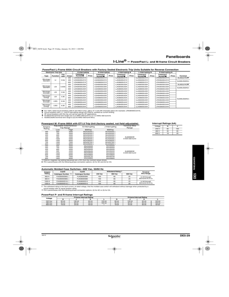
DE5_NEW.book Page 29 Friday, January 18, 2013 1:00 PM Panelboards I-Line® – PowerPact L- and M-frame Circuit Breakers PowerPact L-Frame 600A Circuit Breakers with Factory Sealed Electronic Trip Units Suitable for Reverse Connection Electronic Trip Unit Type Function Trip Unit Micrologic Standard LI 3.3★ Micrologic Standard Micrologic Ammeter LSI LSI 3.3S★ 5.3A Micrologic Energy LSI 5.3E Micrologic Ammeter LSIG 6.3A Micrologic Energy LSIG 6.3E ■ ◆ ★ ▼ s J Interrupting ◆ G Interrupting L Interrupting ◆ R Interrupting ◆ D Interrupting Catalogue Number■ Price LDA36250U31X Catalogue Number■ LGA36250U31X 400 LDA36400U31X LGA36400U31X LJA36400U31X LLA36400U31X LRA36400U31X 600 LDA36600U31X LGA36600U31X LJA36600U31X LLA36600U31X LRA36600U31X 250 LDA36250U33X LGA36250U33X LJA36250U33X LLA36250U33X LRA36250U33X 400 LDA36400U33X LGA36400U33X LJA36400U33X LLA36400U33X LRA36400U33X Amps 250 Catalogue Number■ LJA36250U31X Price Price Catalogue Number■ LLA36250U31X Price Catalogue Number■ LRA36250U31X 600 LDA36600U33X LGA36600U33X LJA36600U33X LLA36600U33X LRA36600U33X 400 LDA36400U43X LGA36400U43X LJA36400U43X LLA36400U43X LRA36400U43X 600 LDA36600U43X LGA36600U43X LJA36600U43X LLA36600U43X LRA36600U43X 400 LDA36400U53X LGA36400U53X LJA36400U53X LLA36400U53X LRA36400U53X 600 LDA36600U53X LGA36600U53X LJA36600U53X LLA36600U53X LRA36600U53X 400 LDA36400U44X LGA36400U44X LJA36400U44X LLA36400U44X LRA36400U44X 600 LDA36600U44X LGA36600U44X LJA36600U44X LLA36600U44X LRA36600U44X 400 LDA36400U54X LGA36400U54X LJA36400U54X LLA36400U54X LRA36400U54X 600 LDA36600U54X LGA36600U54X LJA36600U54X LLA36600U54X LRA36600U54X Price Terminal AL400L61K3▼ AL600LS52K3s AL400L61K3▼ AL600LS52K3s AL600LS52K3s For 100% rated circuit breakers (250 A and 400 A only), add a “C” in the 9th character place (for example, LRA36400CU31X). Circuit breakers with J, L, and R interrupting ratings are CSA/UL certified as current limiting. 3P circuit breakers with this trip unit can be used for 2P applications. AL400L61K3 terminal wire ranges are (1) 2 AWG–600 kcmil Cu or 1) 2 AWG–500 kcmil Al. AL600LS52K3 terminal wire range is (2) 2/0 AWG–500 kcmil Al/Cu. Interrupt Ratings (kA) Powerpact M -Frame 800A with ET1.0 Trip Unit (factory sealed, not field adjustable) G Interrupting J Interrupting 600Vac Terminal Wire Range 600Vac 300 600 3000 MGA26300( ) MJA26300( ) MGA26350( ) MJA26350( ) 350 700 3500 400 800 4000 MGA26400( ) MJA26400( ) 450 900 4500 MGA26450( ) MJA26450( ) 500 1000 5000 MGA26500( ) MJA26500( ) 600 1200 6000 MGA26600( ) MJA26600( ) 700 1400 7000 MGA26700( ) MJA26700( ) 800 1600 8000 MGA26800( ) MJA26800( ) 300 600 3000 MJA36300 MGA36300 350 700 3500 MJA36350 MGA36350 400 800 4000 MJA36400 MGA36400 450 900 4500 MJA36450 MGA36450 MGA36500 500 1000 5000 MJA36500 MGA36600 600 1200 6000 MJA36600 MGA36700 700 1400 7000 MJA36700 MGA36800 800 1600 8000 MJA36800 ❍ CSA/UL magnetic trip setting tolerances are ±10% from the nominal values shown. ✱ Fill in parentheses with the following phase connection options: (2) for AC and (5) for CA. Voltage G J 240 V 65 100 480 V 35 65 600 V 18 25 AL800M23K 3-#3/0-500 kcmil AL800M23K 3-#3/0-500 kcmil PANELBOARDS Ampere Rating Adjustable Instantaneous Trip Range Low High Automatic Molded Case Switches—600 Vac, 50/60 Hz 2-pole 3-pole Catalogue Number ❐ Catalogue Number 240 Vac 480 Vac 600 Vac 600 A PJA26000S60( ) PJA36000S60 100 65 25 800 A PJA26000S80( ) PJA36000S80 100 65 25 3–3/0 through 500 kcmil Al or Cu 1000 A 1200 A PJA26000S10( ) PJA26000S12( ) PJA36000S10 PJA36000S12 100 100 65 65 25 25 4–3/0 through 500 kcmil Al or Cu Terminal Wire Range DE5 Withstand Rating h Ampere Rating h The withstand rating is the fault current, at rated voltage, that the molded case switch will withstand without damage when protected by a circuit breaker with an equal ampere rating. ❐ Fill in parentheses with the following phase connection options: (2) for AC or (5) for CA. PowerPact P- and R-frame Interrupt Ratings Voltage 240 Vac 480 Vac 600 Vac 06/12 G 65 kA 35 kA 18 kA P-frame Interrupt Rating J K 100 kA 65 kA 65 kA 50 kA 25 kA 50 kA L 125 kA 100 kA --- G 65 kA 35 kA 18 kA R-frame Interrupt Rating J K 100 kA 65 kA 65 kA 65 kA 25 kA 65 kA L 125 kA 100 kA 50 kA DE5-29 17607book.fm Page 6 Monday, September 10, 2012 12:51 PM Selection Information Molded Case Circuit Breakers Class 600, 612, 800 PowerPact 800 A M-Frame PowerPact 1200 A P-Frame PowerPact 3000 A R-Frame Circuit Breaker Type MG MJ PG PJ PK PL RG RJ RK RL Number of Poles 2, 3 2, 3 2, 3, 4 2, 3, 4 2, 3, 4 2, 3, 4 2, 3, 4 2, 3, 4 2, 3, 4 2, 3, 4 300–800 300–800 100–1200 100–1200 100–1200 100–1200 240–3000 240–3000 240–3000 240–3000 240 Vac 65 100 65 100 65 125 65 100 65 125 480Y/277 Vac 35 65 35 65 50 100 35 65 65 100 100 Current Range DE3 CIRCUIT BREAKERS Interrupting Ratings UL/CSA/NOM Rating (kA RMS) (50/60 Hz) 480 Vac 35 65 35 65 50 100 35 65 65 600Y/347 Vac 18 25 18 25 50 25 18 25 65 50 600 Vac 18 25 18 25 50 25 18 25 65 50 — 250 Vdc — — — — — — — — — 500 Vdca — — — — — — — — — — 240 Vac 50/25 65/35 50/25 65/35 50/25 125/65 50/25 65/35 85/65 125/65 415 Vac 35/20 50/25 35/20 50/25 50/25 85/45 35/20 50/25 70/55 85/45 CCC X X X X X X X X X X Fed. Specs W-C-375B/GEN X X X X X X X X X X HACR (2P, 3P) X X X X X X X X X X DC Ratings IEC (kA RMS) Icu/lcsb Special Ratings Connections/Terminations Unit Mount X X X X X X X X X X I-Line™ X X X X X X Xe Xe Xe Xe Rear Connection — — — — — — — — — — Drawout — — Xd Xd Xd Xd — — — — Optional Lugs X X X X X X X X X X Accessories and Modifications Shunt Trip X X X X X X X X X X Undervoltage Trip X X X X X X X X X X Auxiliary Switches X X X X X X X X X X Alarm Switch X X X X X X X X X X Motor Operator — — Xd Xd Xd Xd — — — — Handle Operators — — Xd Xd Xd Xd — — — — Mechanical Interlocks (3P) — — X X X X — — — — Handle Padlock Attachment X X X X X X X X X X Cylinder Lock (3P) — — — — — — — — — — Optional GF Protection — — X X X X X X X X Trip System Type Thermal-magnetic — — — — — — — — — — Instantaneous-only (MCP) — — — X X — — — — — Molded Case Switch (Automatic) — — X X X X X X X X Electronic X X X X X X X X X X Enclosures (Pages DE3-56–DE3-58) General Purpose (NEMA 1) X X X X X X — — — — Raintight (NEMA 3R) X X X X X X — — — — Dust-tight (NEMA 12) X X X X X X — — — — Watertight (NEMA 4, 4X, 5) X X — — — — — — — — Explosion Proof (NEMA 7, 9) — — — — — — — — — — Dimensions (3P Unit Mount) Height–in. (mm) 12.80 (325) 16.20 (413) 15 (381) Width—in. (mm) 8.30 (210) 8.30 (210) 16.50 (420) Depth—in. (mm) 8.10 (205) 8.10 (205) Pages (Unit Mount)/(I-Line) Page DE3-26/Section DE5 Page DE3-27, DE3-31, DE3-34/Section DE5 Note: All circuit breakers on this chart are UL Listed and CSA Certified unless otherwise noted. a Ungrounded UPS systems only. See page DE3-35. b Dual CSA/UL and IEC ratings and CE markings on circuit breakers. c Requires breaker with WB suffix d 65/50 kA Icu/Ics for 450–600 A ratings. e 1000 A and 1200 A only. DE3-6 14.40 (366) Page DE3-28, DE3-34/Section DE5 06/12 17607book.fm Page 55 Monday, September 10, 2012 12:51 PM Dimensions and Shipping Weights Molded Case Circuit Breakers Figure 25 Figure 26 B B G F A HD, HG, HJ, HL, HR, JD, JG, JJ, JL, JR, LG, LJ, LL, and LR Circuit Breakers E Circuit Breaker No. of Cat. No. Poles Fig. No. A Prefix 2 25 6.40 HD, HG, HJ*, HL*, HR 3 26 6.40 JD*, JG*, JJ*, 3 27 7.52 JL*, JR LG, LJ, LL, LR 3 28 13.38 F A D E C Dimensions — Inches B C D E F G 2.74 4.12 2.87 2.87 4.36 4.36 0.74 0.74 4.92 4.92 — 1.38 4.12 2.87 5.00 1.30 4.92 1.38 5.51 3.75 6.61 2.22 8.93 1.77 * - The HJ, HL and the J-Frame 2P breakers are 3P modules Figure 27 B G ED, EG and EJ Circuit Breakers C ED, EG, EJ E GJ Figure 28 F B E A E 29 0.98 5.66 3.09 4.05 3.32 30 1.96 5.66 3.09 4.05 3.32 3 30 2.94 5.66 3.09 4.05 3.32 3 32 3.54 4.72 2.76 3.94 2.20 No. of Poles Fig. No. A B E C D E F G MG, MJ (800 A and below) PG, PJ, PK, PL (1000–1200 A) RG, RJ, RL 2, 3 33 12.86 8.27 5.77 8.05 2.49 7.87 7.83 2, 3 33 16.16 8.27 5.77 8.05 4.19 7.87 7.83 2, 3 34 16.24 16.54 6.63 14.49 8.73 14.25 15.35 2 Frame Size JD, JG, JJ, JL, JR LD, LG, LJ, LL, LR Approx. Shipping Weight (Lbs.) 5 14 29 MG, MJ ED, EG, EJ 2P 3 PG, PJ, PK, PL ED, EG, EJ 3P 4 RG, RJ, RK, RL (Without RLTB) a All weights are for 3P circuit breakers unless otherwise noted. B A A Dimensions — Inches Approx. Shipping Weight (Lbs.) HD, HG, HJ, HL 2P 4 HD, HG, HJ, HL, HR 3P 5 Figure 31 32 52 C D Figure 33 Figure 32 B G E D Frame Size Figure 30 B C Circuit Breaker Cat. No. Prefix ED, EG, EJ 1P E 2 B Shipping Weightsa B D Figure 29 1 A MG, MJ, PG, PJ, PL, RG, RJ and RL Circuit Breakers G A C Fig. No. D C E B AF A C D E Figure 34 B G F D C AE 06/12 DE3-55 CIRCUIT BREAKERS A Dimensions — Inches No. of Poles DE3 D F Circuit Breaker Catalogue No. Prefix


