Page 1 www.ifdcorporation.com NO FAULT FAULT With over a half
advertisement

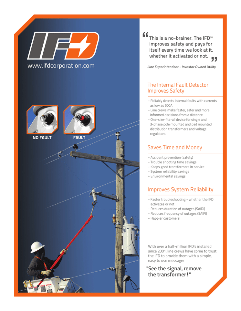
“ www.ifdcorporation.com This is a no-brainer. The IFD™ improves safety and pays for itself every time we look at it, whether it activated or not. ” Line Superintendent - Investor Owned Utility The Internal Fault Detector Improves Safety NO FAULT FAULT - Reliably detects internal faults with currents as low as 500A - Line crews make faster, safer and more informed decisions from a distance - One-size-fits-all device for single and 3-phase pole mounted and pad mounted distribution transformers and voltage regulators Saves Time and Money - Accident prevention (safety) - Trouble shooting time savings - Keeps good transformers in service - System reliability savings - Environmental savings Improves System Reliability - Faster troubleshooting - whether the IFD activates or not - Reduces duration of outages (SAIDI) - Reduces frequency of outages (SAIFI) - Happier customers With over a half-million IFD’s installed since 2001, line crews have come to trust the IFD to provide them with a simple, easy to use message: "See the signal, remove the transformer!" IFD Performance Specifications 1. Certified Transformers Suitable for installation in single and 3-phase pole mounted and pad mounted distribution transformers and voltage regulators. NO FAULT FAULT The IFD™ is a sensor that detects and indicates internal arcing faults in pole mounted and pad mounted distribution transformers. How it Works When a low impedance internal arcing fault occurs the pressure rises rapidly inside the transformer. This sudden pressure rise activates the IFD, releasing a highly visible orange indicator that shows line crews the transformer is potentially dangerous, and must be replaced. 2. Transformer Operation The IFD is located in the airspace above the maximum operating oil level and has no impact on the normal operation of the transformer. Ref.: CEATI Report*. 3. Activation Level The IFD will activate with a minimum pressure rise of 0.5psi in 5-7ms. Cert.: Simulated symmetrical and asymmetrical internal faults from 500A to 8000A. Ref.: CEATI Report*. 4. Pressure Relief The IFD includes an integrated PRV (pressure relief valve) that can be specified to meet either the IEEE of CSA transformer standards with a minimum flow rate of 50 SCFM (23.5 L/s). The PRV also operates with or without the shipping lock installed. Ref.: IEEE C57.12.20; CSA C2.2. 5. Reliable Activation The IFD will only activate during an internal fault in the transformer. The IFD will not activate due to faults external to the transformer or due to normal pressure changes within the transformer. Ref.: CEATI Report*. 6. Operating Temperature Range The IFD will operate between -40°C (-40°F) to 185°C (365°F). Ref.: IFD Engineering. Rapid pressure rise (0.5 psi /5-7ms or larger) The IFD also incorporates a standard pressure relief valve (PRV). Safety Pays In addition to improving worker safety, the maintenance free IFD mechanical sensor provides set-it-and-forget-it operation and a typical 12:1 return on investment over the life of the transformer. Getting Started If you’re ready to start using IFD’s then it’s as simple as adding them to your transformer specification. To help get you started, here’s an IFD specification example from an IFD user: "Each transformer shall be equipped with a non-resettable device which detects and provides external indication of internal transformer faults, and also incorporates pressure relief functionality. The approved device is manufactured by IFD Corporation or approved equal." 7. Service Life The IFD is manufactured from glass reinforced PBT for greater than 30 years of service. The IFD requires no maintenance during its service life. Ref.: CEATI Report*. 8. Visibility The activated IFD is clearly visible from at least 60' (20m) during day or night. Cert.: Day and night visibility test. Ref.: BC Research Inc. 9. Permanent Fault Indication Once activated the IFD cannot be reset. The transformer must be removed from service. 10. Standards The IFD conforms to: IEEE C57.12.20, CSA C2.2, IEC 61936-1. 11. Quality & Testing Every IFD is individually tested in a calibrated chamber to ensure correct operation at the lowest specified activation level. Some examples of additional tests: a. Lightning Impulse An IFD equipped transformer passed the lightning impulse test at a level 16% above the rating. Ref.: CEATI Report*. b. Mechanical Vibration Tests on IFD equipped transformers confirm that providing the shipping lock is properly installed, the signal will not activate during normal transformer transportation or handling. Ref.: CEATI Report*. c. Shipping & Handling The IFD incorporates a removable shipping lock for transportation and storage. This prevents accidental activation of the mechanical sensor. IMPORTANT NOTE: Always transport IFD equipped transformers with the shipping lock installed. Ref.: IFD Engineering. *CEA Technologies Inc. Report #T994700-5003 T 604.734.0105 E info@ifdcorporation.com www.ifdcorporation.com


