Installation Instructions
00809-0600-4975
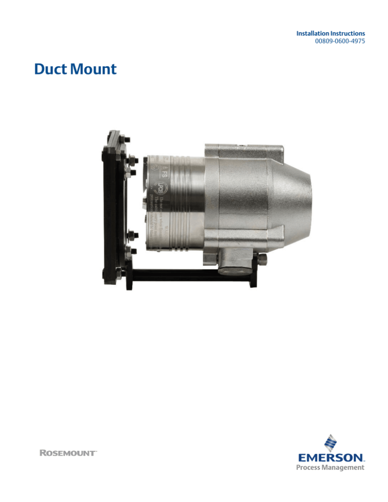
Duct Mount
Legal Notice
The Flame Detector described in this document is the property of Rosemount.
No part of the hardware, software, or documentation may be reproduced, transmitted, transcribed, stored in a retrieval system, or
translated into any language or computer language, in any form or by any means, without prior written permission of Rosemount.
While great efforts have been made to ensure the accuracy and clarity of this document, Rosemount assumes no liability resulting
from any omissions in this document of from misuse of the information obtained herein. The information in this document has been
carefully checked and is believed to be entirely reliable with all of the necessary information included. Rosemount reserves the right
to make changes to any products described herein to improve reliability, function, or design and reserves the right to revise this
document and make changes from time to time in content hereof with no obligation to notify any persons of revisions or changes.
Rosemount does not assume any liability arising out of the application or any use of any product or circuit described herein; neither
does it convey license under its patent rights or the rights of others.
WARNING!
This manual should be read carefully by all individuals who have or will have responsibility for using, maintaining, or servicing the
product.
The Detector is not field repairable due to the meticulous alignment and calibration of the sensors and the respective circuits. Do not
attempt to modify or repair the internal circuits or change their settings, as this will impair the system's performance and void the
Rosemount product warranty.
Warranty
1.
Limited Warranty . Subject to the limitations contained in Section 10 (Limitation of Remedy and Liability) herein, Seller
warrants that (a) the licensed firmware embodied in the Goods will execute the programming instructions provided by
Seller; (b) that the Goods manufactured by Seller will be free from defects in materials or workmanship under normal use
and care; and (c) Services will be performed by trained personnel using proper equipment and instrumentation for the
particular Service provided. The foregoing warranties will apply until the expiration of the applicable warranty period.
Sensors and detectors are warranted against defective parts and workmanship for 24 months from the date of purchase and
other electronic assemblies for 36 months from the date of purchase. Products purchased by Seller from a third party for
resale to Buyer (Resale Products) shall carry only the warranty extended by the original manufacturer. Buyer agrees that
Seller has no liability for Resale Products beyond making a reasonable commercial effort to arrange for procurement and
shipping of the Resale Products. If Buyer discovers any warranty defects and notifies Seller thereof in writing during the
applicable warranty period, Seller shall, at its option, (i) correct any errors that are found by Seller in the firmware or
Services; (ii) repair or replace FOB point of manufacture that portion of the Goods found by Seller to be defective; or (iii)
refund the purchase price of the defective portion of the Goods/Services. All replacements or repairs necessitated by
inadequate maintenance; normal wear and usage; unsuitable power sources or environmental conditions; accident; misuse;
improper installation; modification; repair; use of unauthorized replacement parts; storage or handling; or any other cause
not the fault of Seller, are not covered by this limited warranty and shall be replaced or repaired at Buyer's sole expense and
Seller shall not be obligated to pay any costs or charges incurred by Buyer or any other party except as may be agreed upon
in writing in advance by Seller. All costs of dismantling, reinstallation, freight and the time and expenses of Seller's personnel
and representatives for site travel and diagnosis under this limited warranty clause shall be borne by Buyer unless accepted
in writing by Seller. Goods repaired and parts replaced by Seller during the warranty period shall be in warranty for the
remainder of the original warranty period or 90 days, whichever is longer. This limited warranty is the only warranty made by
Seller and can be amended only in a writing signed by an authorized representative of Seller. The limited warranty herein
ceases to be effective if Buyer fails to operate and use the Goods sold hereunder in a safe and reasonable manner and in
accordance with any written instructions from the manufacturers. THE WARRANTIES AND REMEDIES SET FORTH ABOVE ARE
EXCLUSIVE. THERE ARE NO REPRESENTATIONS OR WARRANTIES OF ANY KIND, EXPRESS OR IMPLIED, AS TO
MERCHANTABILITY, FITNESS FOR PARTICULAR PURPOSE OR ANY OTHER MATTER WITH RESPECT TO ANY OF THE GOODS
OR SERVICES.
2.
Limitation of Remedy and Liability SELLER SHALL NOT BE LIABLE FOR DAMAGES CAUSED BY DELAY IN PERFORMANCE. THE
REMEDIES OF BUYER SET FORTH IN THE AGREEMENT ARE EXCLUSIVE. IN NO EVENT, REGARDLESS OF THE FORM OF THE
CLAIM OR CAUSE OF ACTION (WHETHER BASED IN CONTRACT, INFRINGEMENT, NEGLIGENCE, STRICT LIABILITY, OTHER
TORT OR OTHERWISE), SHALL SELLER'S LIABILITY TO BUYER AND/OR BUYER'S CUSTOMERS EXCEED THE PRICE TO BUYER OF
THE SPECIFIC GOODS MANUFACTURED OR SERVICES PROVIDED BY SELLER GIVING RISE TO THE CLAIM OR CAUSE OF
ACTION. BUYER AGREES THAT IN NO EVENT SHALL SELLER'S LIABILITY TO BUYER AND/OR BUYER'S CUSTOMERS EXTEND TO
INCLUDE INCIDENTAL, CONSEQUENTIAL OR PUNITIVE DAMAGES. THE TERM "CONSEQUENTIAL DAMAGES" SHALL INCLUDE,
BUT NOT BE LIMITED TO, LOSS OF ANTICIPATED PROFITS, REVENUE OR USE AND COSTS INCURRED INCLUDING WITHOUT
LIMITATION FOR CAPITAL, FUEL AND POWER, AND CLAIMS OF BUYER'S CUSTOMERS.
Release History
Revision
Date
Revision History
A
March 2016
First release
Contents
Contents
Chapter 1
General Description ..........................................................................................................1
Chapter 2
Installation Instructions ................................................................................................... 2
Chapter 3
Technical Support ............................................................................................................ 8
i
Contents
ii
General Description
1
General Description
This document describes the installation instructions for the Duct Mount (P/N
00975-9000-0002).
The Duct Mount is suitable for use with the Rosemount 975 Flame Detectors (975MR,
975HR, 975UF, and 975UR) for both the aluminum and stainless steel enclosures.
The Duct Mount allows flame detection in areas where high temperatures exist or in cases
where the detector cannot be installed inside the area. It comprises a special duct mount
arrangement with a specific optical window to allow installation in high temperature duct
applications.
The Duct Mount will limit the cone of vision of the installed detector to 65 ° horizontal and
65 ° vertical.
The temperature allowed for the Duct Mount to be installed at is -67 °F to 392 °F (-55 °C to
200 °C).
1
Installation Instructions
2
Installation Instructions
1.
Prepare the surface (Figure 2-1).
a. Check the air duct installation surface (C) stability. It should be as near as
possible to a riding girder connection in order to ensure proper support to the
mounting and to the unit. Also, the surface must be stable and free of vibrations.
b. Locate the best installation surface for the detector, so that the detector will
have a full cone of vision to the protected area.
c. Drill the duct hole (B) and the screw holes (A) carefully.
Figure 2-1: Drilling layout dimensions for duct installation
A. Screw holes
B. Duct hole
C. Duct installation surface
2.
Disassemble the Duct Mount.
a. See Figure 2-2. Open nuts(B and D) and washers (A and C).
2
Installation Instructions
Figure 2-2: Duct Mount disassembly
A.
B.
C.
D.
4 spring washers M6
4 plate nuts M6
4 spring washers M6
4 base nuts M6
3
Installation Instructions
b. See Figure 2-3. Dismount internal plate (A) and base plate (B).
Figure 2-3: Duct Mount parts
A.
B.
C.
D.
E.
F.
G.
3.
2 internal plates
Base plate
4 spring washers M6
4 plate nuts M6
Duct mount base
4 spring washers M6
4 base nuts
Mount the Duct Mount (Figure 2-4)
a. Insert the first internal plate (A) through the air duct hole (C).
b. Hold the first internal plate (A) by hand and press the base plate (E) to the
installation surface against the internal plate.
At the base plate (E), there is a gasket, which is glued.
c. Insert the internal plate screws into the gasket holes to prevent the internal plate
from falling.
d. Secure the baseplate to the installation surface using four nuts (G) and washers
(F).
e. Remove your hand and repeat substeps A-D for the second internal plate.
f. Attach the duct mount base (H) to the base plate (E) and secure it with washers
(I) and nuts (J).
4
Installation Instructions
Figure 2-4: Duct Mount parts before final assembly
A.
B.
C.
D.
E.
F.
G.
H.
I.
J.
Two internal plates
Screw holes
Air duct hole
Duct installation surface
Base plate
4 spring washers M6
4 plate nuts M6
Duct mount base
4 spring washers M6
4 base nuts M6
The base plate (E) and duct mount base (H) are now connected. See Figure 2-5.
5
Installation Instructions
Figure 2-5: Duct Mount parts after assembly
4.
6
Mount the detector (Figure 2-6). Insert the detector (A) at pin (B) and secure it using
a screw (C).
Installation Instructions
Note
The screw (C) is already mounted on the detector and should be removed and reinstalled
facing the other direction.
Figure 2-6: Detector mounted on Duct Mount
A. Detector
B. Pin
C. Screw
7
Technical Support
3
Technical Support
For all technical assistance or support contact:
Emerson Process Management
6021 Innovation Boulevard
Shakopee, MN 55379-9795
U.S.A.
T +1 866 347 3427
F +952 949 7001
SAFETY.CSC@Emerson.com
8
Technical Support
9
00809-0600-4975
www.EmersonProcess.com/FlameGasDetection
Rosemount
6021 Innovation Blvd.
Shakopee, MN 55379
Toll Free + 866 347 3427
F +1 952 949 7001
safety.csc@emerson.com
www.EmersonProcess.com/FlameGasDetection
EUROPE
Emerson Process Management
Neuhofstrasse 19a P.O. Box 1046
CH-6340 Baar
Switzerland
T + 41 (0) 41 768 6111
F + 41 (0) 41 768 6300
safety.csc@emerson.com
www.EmersonProcess.com/FlameGasDetection
MIDDLE EAST AND AFRICA
Emerson Process Management
Emerson FZE
Jebel Ali Free Zone
Dubai, United Arab Emirates, P.O. Box 17033
T +971 4 811 8100
F +971 4 886 5465
safety.csc@emerson.com
www.EmersonProcess.com/FlameGasDetection
ASIA-PACIFIC
Emerson Process Management
Asia Pacific Private Limited
1 Pandan Crescent
Singapore 128461
Singapore
T +65 777 8211
F +65 777 0947
safety.csc@emerson.com
www.EmersonProcess.com/FlameGasDetection
©2016 Rosemount. All rights reserved.
The Emerson logo is a trademark and service mark of Emerson
Electric Co. Rosemount is a mark of one of the Emerson Process
Management family of companies. All other marks are the property
of their respective owners. The contents of this publication are
presented for information purposes only, and, while effort has been
made to ensure their accuracy, they are not to be construed as
warranties or guarantees, express or implied, regarding the
products or services described herein or their use or applicability.
All sales are governed by our terms and conditions, which are
available on request. We reserve the right to modify or improve the
designs or specifications of our products at any time without
notice.


