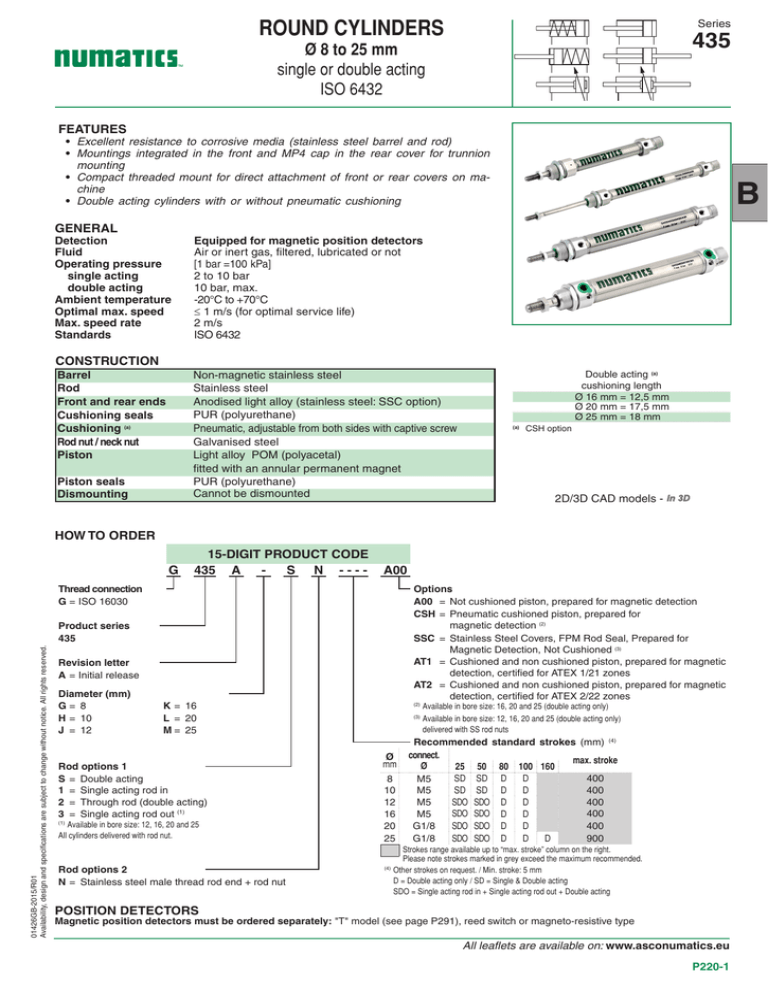
ROUND CYLINDERS
Series
435
Ø 8 to 25 mm
single or double acting
ISO 6432
FEATURES
• Excellent resistance to corrosive media (stainless steel barrel and rod)
• Mountings integrated in the front and MP4 cap in the rear cover for trunnion
mounting
• Compact threaded mount for direct attachment of front or rear covers on machine
• Double acting cylinders with or without pneumatic cushioning
B
GENERAL
Detection
Equipped for magnetic position detectors
Fluid
Air or inert gas, filtered, lubricated or not
Operating pressure
[1 bar =100 kPa]
single acting
2 to 10 bar
double acting
10 bar, max.
Ambient temperature
-20°C to +70°C
Optimal max. speed
≤ 1 m/s (for optimal service life)
Max. speed rate
2 m/s
Standards
ISO 6432
CONSTRUCTION
Barrel
Rod
Front and rear ends
Cushioning seals
Cushioning (a)
Rod nut / neck nut
Piston
Non-magnetic stainless steel
Stainless steel
Anodised light alloy (stainless steel: SSC option)
PUR (polyurethane)
Pneumatic, adjustable from both sides with captive screw
Galvanised steel
Light alloy POM (polyacetal)
fitted with an annular permanent magnet
PUR (polyurethane)
Cannot be dismounted
Piston seals
Dismounting
Double acting (a)
cushioning length
Ø 16 mm = 12,5 mm
Ø 20 mm = 17,5 mm
Ø 25 mm = 18 mm
CSH option
(a)
2D/3D CAD models - In 3D
HOW TO ORDER
G
15-DIGIT PRODUCT CODE
435 A
S N ----
A00
Thread connection
G=ISO 16030
Options
A00=Not cushioned piston, prepared for magnetic detection
CSH=Pneumatic cushioned piston, prepared for
magnetic detection (2)
SSC=Stainless Steel Covers, FPM Rod Seal, Prepared for
Magnetic Detection, Not Cushioned (3)
AT1 =Cushioned and non cushioned piston, prepared for magnetic
detection, certified for ATEX 1/21 zones
AT2 =Cushioned and non cushioned piston, prepared for magnetic
detection, certified for ATEX 2/22 zones
01426GB-2015/R01
Availability, design and specifications are subject to change without notice. All rights reserved.
Product series
435
Revision letter
A=Initial release
Diameter (mm)
G= 8
H= 10
J=12
K= 16
L=20
M= 25
Rod options 1
S=Double acting
1=Single acting rod in
2=Through rod (double acting)
3=Single acting rod out (1)
(1)
Available in bore size: 12, 16, 20 and 25
All cylinders delivered with rod nut.
Rod options 2
N= Stainless steel male thread rod end + rod nut
Ø
mm
8
10
12
16
20
25
(2)
Available in bore size: 16, 20 and 25 (double acting only)
(3)
vailable in bore size: 12, 16, 20 and 25 (double acting only)
A
delivered with SS rod nuts
Recommended standard strokes (mm) (4)
connect.
max. stroke
Ø
25 50 80 100 160
400
SD SD D
D
M5
M5
400
SD SD D
D
M5
400
SDO SDO D
D
400
SDO SDO D
M5
D
G1/8
400
SDO SDO D
D
G1/8
900
SDO SDO D
D
D
Strokes range available up to “max. stroke” column on the right.
Please note strokes marked in grey exceed the maximum recommended.
(4)
O
ther strokes on request. / Min. stroke: 5 mm
D = Double acting only / SD = Single & Double acting
SDO = Single acting rod in + Single acting rod out + Double acting
POSITION DETECTORS
Magnetic position detectors must be ordered separately: "T" model (see page P291), reed switch or magneto-resistive type
All leaflets are available on: www.asconumatics.eu
P220-1
ISO 6432 ROUND CYLINDERS - SERIES 435
INSTALLATION
• The cylinders can be mounted in any position without affecting operation
• Each cylinder is delivered with a neck nut and a rod nut
• Mountings: catalogue number
Ø
(mm)
MF8
steel
8 - 10
12 - 16
20
25
st. steel
Rear
trunnion
High foot
(per unit)
MS3
Front or rear flange
steel
st. steel
P493AG42A000A00
P493AG425000A00
P493AJ42A000A00 P493AJ42A200A00 P493AJ425000A00
P493AL42A000A00 P493AL42A200A00 P493AL425000A00
P493AL42A000A00 P493AL42A200A00 P493AL425000A00
steel
st. steel
P493AG42C000A00
P493AJ425200A00 P493AJ42C000A00 P493AJ42C200A00
P493AL425200A00 P493AL42C000A00 P493AL42C200A00
P493AL425200A00 P493AL42C000A00 P493AL42C200A00
Ø
(mm)
8 - 10
12 - 16
20
25
female rod clevis
ISO 8140 - RP 102 P
AP2
steel
st. steel
spherical rod end
ISO 8139 - RP 103 P
AP6
steel
P493AG431000A00
P493AJ431000A00 P493AJ431200A00
P493AL431000A00 P493AL431200A00
P493A3131000A00 P493AM431200A00
P493AG432000A00
P493AJ432000A00
P493AL432000A00
P493A3132000A00
front neck nut
MR3
steel
st. steel
P493AG42F000A00
P493AJ42F000A00 P493AJ42F200A00
P493AL42F000A00 P493AL42F200A00
P493AL42F000A00 P493AL42F200A00
01426GB-2013/R01
Availability, design and specifications are subject to change without notice. All rights reserved.
• Pipe connections G 1/8 have standard thread according to ISO 16030
• Installation/maintenance instructions are included with each cylinder
All leaflets are available on: www.asconumatics.eu
P220-2
ISO 6432 ROUND CYLINDERS - SERIES 435
DIMENSIONS (mm), WEIGHT (kg)
SINGLE-ROD TYPE CYLINDER
THROUGH-ROD TYPE CYCLINDER
Bare cylinder, single and double acting
Supplied with front cover nut
ISO 6432
T+ 1
ZB + 1
XC + 1
PJ + 1
F+ 1
AM
Y
WH
BF
ØEE
ØEE
ZM + 2
AM
BC
ØEE
ØCD
ØBE
ØMM
ØKK
Z 3
ØBE
BC
1 Stroke
EW
BC
L
2 Stroke x 2
3 Width across flats
L
EW
Ø
AM
B
BC
8
10
12
16
20
25
12
12
16
16
20
22
16
16
19
19
27
30
12
12
14
14
17,5
17,5
Ø
Z
ZB
ZM
8
10
12
16
20
25
7
74
0,030
7
74
0,030
10 84,5 82,5 0,070
10 91
99 0,100
13 105 111,5 0,170
17 114 124,5 0,200
ØBE
BF
ØCD
M12x1,25 12
4H9
M12x1,25 12
4H9
M16x1,5 14 6 H 11
M16x1,5 14 6 H 11
M22x1,5 17,5 8 H 11
M22x1,5 17,5 8 H 11
ØEE
15 M5
15 M5
18 M5
18 M5
25,4 G 1/8
28,5 G 1/8
EW
F
F1
ØKK
8 d 13 46
M4x0,7
8 d 13 46
M4x0,7
12 d 11 48,5 48,5 M6x1
12 d 11 55 55
M6x1
16 d 11 63,5 63,5 M8x1,25
16 d 11 68,5 68,5 M10x1,25
(5)
0,020
0,040
0,090
0,100
0,160
0,200
UF1
Y
AM
12 65
12 65
16 74,5
16 81,0
20 92,5
22 101,5
T
WH
XC
Y
6
6
9
9
12
12
4
4
6
6
8
10
34
34
34,5
41,5
47,3
52,5
34,5
41,5
47,3
52,5
2
2
3
3
4
5
86
86
100,3
107
125
136
16
16
22
22
24
28
64
64
75
82
95
104
22
22
29
28,5
32
36
AM
ZF + 1
Y
W ØFB UF TF UR
weight
3
3
4
4
5
5
22
22
22
22
31
31
13
13
18
18
19
23
0,020
0,020
0,020
0,020
0,040
0,040
40
40
52
52
64
64
30
30
40
40
50
50
22
22
30
30
40
40
SA’ +
SA +
XA +
LA +
1
1
1
1
AO
1 Stroke
MF
4,5
4,5
5,5
5,5
6,6
6,6
AU
XS
2 Ø AB
W
=
AM
ZF
S
NH/AH
=
TF
=
=
TR
=
=
US
=
=
=
Ø
(mm)
08
10
12
16
20
25
PK
High foot
Foot mounting are supplied in single units,
not in pairs
MS3
MF
MF
1 Stroke
PJ
MOUNTING
2 Ø FB
UR
MM
NOTE:
- Single and double acting Rod-In have the same dimensions.
- Use twice Nominal Stroke for Single Acting Rod Out.
- The mountings are always delivered separately
Front or rear flange
MF8
=
L
(4) Cylinder weight at 0 mm stroke.
(5) Weight to be added per additional 100 mm length.
weight
(4)
D
MOUNTING
UF
AM
PK + 1
MF
D
EW
B
01426GB-2016/R01
Availability, design and specifications are subject to change without notice. All rights reserved.
WH + 1
F1 + 1
WH
ØBE
S
Bare cylinder, double acting
Supplied with front cover nut
ISO 6432
Ø
(mm) UF1
08 26
10 26
12 32
16 32
20 45
25 45
NH
AH
16
16
20
20
25
25
TR US MF ØAB AM AU XS SA SA' XA
25
25
32
32
40
40
35
35
42
42
54
54
3
3
4
4
5
5
4,5
4,5
5,5
5,5
6,6
6,6
12
12
16
16
20
22
11
11
14
14
17
17
LA AO weight
24 68 30 73 78
5
24 68 30 73 78
5
32 76,5 28,5 84,5 90,5 6
32 83 35 91 97
6
36 97,5 39,5 104,5113,5 9
40 102,5 44,5 113,5122,5 9
0,030
0,030
0,050
0,050
0,100
0,100
All leaflets are available on: www.asconumatics.eu
P220-3
B
ISO 6432 ROUND CYLINDERS - SERIES 435
DIMENSIONS (mm), WEIGHT (kg)
MOUNTING
MOUNTING
Female rod clevis
ISO 8140
AP2 (steel)
Rear trunnion
FA + 1
X
ØCK H9/d10
K max.
CM
CL
Ø
(mm)
8-10
12
16
20
25
2ØFB
α
AM BH EA FA FB GA GC GG GL UA UB X
12
16
16
20
20
24
27
27
30
30
62,7
72,5
79,5
91
100
79
93
100
117
126
4,5
5,5
5,5
6,6
6,6
20
25
25
32
32
2,5 12,5
3 16
3 16
4 20
4 20
29
34
34
40
40
18
25
25
32
32
13
18
18
24
24
AV
GA
GG
EA + 1
11,2
13,5
13,5
16
16
ω
7° 160°
50° 180°
47° 180°
8° 168°
8° 168°
ØKK
weight
0,020
0,050
0,050
0,080
0,080
Ø
Ø
(mm) CK
8-10 4
12-16 6
20 8
25 10
MOUNTING
CM
4 ++ 0,4
0,1 11
6 ++ 0,4
0,1 16,5
0,5
8 ++ 0,15
22
0,5
10 ++ 0,15
26
ØCN H9
EN h12
K
CL
CM
AX
AV
B
CE1
CE
27
30
36
43
5
6
8
10
10
11
13
15
ØKK
EN
α
weight
M4x0,7
M6x1
M8x1,25
M10x1,25
8
9
12
14
4°
4°
4°
4°
0,020
0,030
0,050
0,070
MOUNTING
Front neck nut
MR3
ØBE
KV
Ø
(mm)
8
10
12
16
20
25
KW
ØBE
M12x1,25
M12x1,25
M16x1,5
M16x1,5
M22x1,5
M22x1,5
KV KW
weight
19
19
19
19
27
27
0,010
0,010
0,010
0,010
0,010
0,010
6
6
4
4
5
5
All leaflets are available on: www.asconumatics.eu
P220-4
E max.
LE
36
40
48
57
0,010
0,020
0,050
0,100
Ø CK H9/d10
LE1
ER max.
8
12
15
20
16
24
32
40
CL
α α
B CE1 ØCN LE1
8
12
16
20
weight
Female rod clevis
ISO 8140
AP2 (stainless steel)
ØKK
AX
8
12
15
20
ØKK
MOUNTING
Spherical rod end
ISO 8139
AP6 (steel)
Ø
(mm)
8-10
12-16
20
25
E
max.
8 M4x0,7 22,5
12 M6x1 33,5
16 M8x1,25 45
20 M10x1,25 56
K AV LE CE CL
Ø KK
Ø
(mm)
8-10
12-16
20
25
CL
max.
8
12
16
20
ØKK
E AV
CM ØCN max.
min.
M4x0,7
4
M6x1
6
M8x1,25
8
M10x1,25 10
4
6
8
10
21
31
42
52
10
12
16
20
LE
CE
weight
8
12
16
20
16
24
32
40
0,005
0,015
0,036
0,075
01426GB-2014/R01
Availability, design and specifications are subject to change without notice. All rights reserved.
UB
= =
1 Stroke
CE
LE
BH
GC
GL
UA
= =
E max.
AM


