Experiment 41: Three Phase Power / Wye Connection
Introduction
This lab experiment requires a low-voltage 3-phase voltage source that can supply a 12V peakto-peak sine wave at a current of at least 25mA rms per phase. One can be built on a
breadboard as described in Appendix 2. A compact plug-in version of this 3-phase source is
described in this lab experiment and also in Appendix 2.
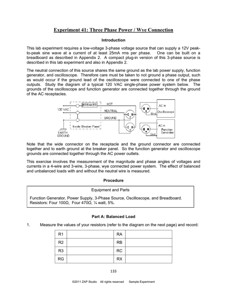
The neutral connection of this source shares the same ground as the lab power supply, function
generator, and oscilloscope. Therefore care must be taken to not ground a phase output, such
as would occur if the ground lead of the oscilloscope were connected to one of the phase
outputs. Study the diagram of a typical 120 VAC single-phase power system below. The
grounds of the oscilloscope and function generator are connected together through the ground
of the AC receptacles.
Note that the wide connector on the receptacle and the ground connector are connected
together and to earth ground at the breaker panel. So the function generator and oscilloscope
grounds are connected together through the AC power outlets.
This exercise involves the measurement of the magnitude and phase angles of voltages and
currents in a 4-wire and 3-wire, 3-phase, wye connected power system. The effect of balanced
and unbalanced loads with and without the neutral wire is measured.
Procedure
Equipment and Parts
Function Generator, Power Supply, 3-Phase Source, Oscilloscope, and Breadboard.
Resistors: Four 100Ω, Four 470Ω, ¼ watt, 5%.
Part A: Balanced Load
1.
Measure the values of your resistors (refer to the diagram on the next page) and record:
R1
RA
R2
RB
R3
RC
RG
RX
133
©2011 ZAP Studio
All rights reserved
Sample Experiment
If you already have a 3-phase voltage source, set it to produce a 60Hz, 12V peak-topeak, sine wave per phase, as measured from each line output to neutral.
The
reference phase will be P0 in this experiment. The phase angle of P1 will be 1200 with
reference to P0 and the phase angle of P2 will be -1200 with reference to P0.
Check that the voltages and phase angles of the 3-phase source are correct.
2.
If you don’t already have a 3-phase voltage source, you can build the circuit described in
appendix 2, or use a pc board version of the circuit, the Phase Tripler, or the Phase
Tripler II, which are also described in appendix 2.
Connect the circuit as shown below. The circuit connected on a breadboard with the
Phase Tripler II is shown on the right.
If you are using the Phase Tripler II board, handle it by the edges and carefully insert it
into the breadboard. Connect the power supply ground and function generator ground
to pin 2, function generator signal to pin 1, +12VDC to pin 4, and -12VDC to pin 6.
Connect the output pins to the circuit. Pin 9 is P0, pin 10 is P1, pin 11 is P2, and P12 is
neutral (ground). Also connect the oscilloscope grounds to pin 12.
If you are using the Phase Tripler, the same inputs are required except banana binding
posts are used for the DC inputs and phase outputs. The function generator is
connected to the BNC.
3.
Connect channel 1 of the oscilloscope to P0 and set the trigger to channel 1. Set the
function generator amplitude to produce a 12V peak-to-peak sine wave with no offset on
channel 1.
4.
Connect channel 2 of the oscilloscope to P1. Check that the amplitude is exactly
12V peak-to-peak and that the phase is leading channel 1 by exactly 1200.
5.
Connect channel 2 of the oscilloscope to P2. Check that the amplitude is exactly
12V peak-to-peak and that the phase is lagging channel 1 by exactly 1200.
[Refer to the calibration procedure in Appendix 2 if steps 3 and 4 don’t check.]
If you are using a different 3-phase source, record the magnitude and phase angle of the
voltage supplying phases A, B, and C of the load circuit.
134
©2011 ZAP Studio
All rights reserved
Sample Experiment
6.
Measure the magnitude and phase angle of the voltages VG, VA, VB, and VC with
channel 2. Record results below.
Step 6
VG
VA
VB
VC
Magnitude p-p
Phase, Deg.
7.
Open the neutral line by removing the 100Ω resistor between the phase tripler ground
and node VG.
8.
Measure the magnitudes and phase angles of the voltages VG, VA, VB, and VC with
the oscilloscope channel 2 and record results in the table below.
Step 8
VG
VA
VB
VC
VB
VC
Magnitude p-p
Phase, Deg.
Part B: Unbalanced Load
1.
Connect a 470Ω resistor (RX) in parallel
with RC so that the RC branch
becomes 235Ω, as shown on the right.
Reconnect the 100Ω resistor between
node VG and COMMON.
2.
Measure the magnitudes and phase
angles of the voltages VG, VA, VB, and
VC with oscilloscope channel 2 and
record results in the table below.
Step 2
VG
VA
Magnitude p-p
Phase, Deg.
3.
Open the neutral line by removing the 100Ω resistor between the phase tripler ground
and node VG.
4.
Measure the magnitude and phase angle of the voltages at nodes nG, nA, nB, and nC
with the oscilloscope channel 2 and record results in the table below.
Step 4
VG
VA
VB
Magnitude p-p
Phase, Deg.
135
©2011 ZAP Studio
All rights reserved
Sample Experiment
VC
Analysis, Part A
1.
Use your measured resistor values and the node voltage method to calculate the voltage
VG for the circuit used in procedure part A. Use the result to calculate the current
supplied by the source for each phase (both magnitude and phase angle).
2.
Calculate the magnitudes and phases angles of the voltages VA, VB, and VC. Calculate
the neutral wire current.
3.
Calculate the percent error between the measured and calculated values of the voltage
magnitudes VA, VB, and VC. Calculate the absolute error between the phase angles.
Analysis, Part B
1.
Use LTspice to simulate the unbalanced circuit with and without the neutral connection.
Refer to the example below.
2.
Calculate the percent error between the measured and simulated values of the voltage
magnitudes VA, VB, and VC. Calculate the absolute error between the phase angles.
3.
Use Kirchhoff’s current law to show that the neutral wire current is the result of the
unbalance of the phase currents.
LTspice 3-Phase Analysis
Three phase circuits can be simulated using three voltage
sources. Right click on each source and set their AC
Amplitude and phase angle.
Use AC analysis with the start and stop frequencies set to
60Hz and the number of points set to 1.
Use your measured resistor values for your simulation.
The results of simulating the circuit on the right are given
below. Verify for yourself that the current supplied by
each source is 20mA p-p.
136
©2011 ZAP Studio
All rights reserved
Sample Experiment


