MAXPRO ® NVR SE NIC Card Installation
Application Note
An optional second Network Interface Controller (NIC) card can be ordered for your MAXPRO
NVR SE Unit. This application note explains how to install the NIC card.
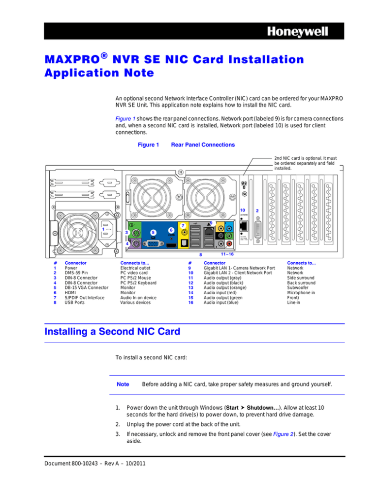
Figure 1 shows the rear panel connections. Network port (labeled 9) is for camera connections
and, when a second NIC card is installed, Network port (labeled 10) is used for client
connections.
Figure 1
Rear Panel Connections
2nd NIC card is optional. It must
be ordered separately and field
installed.
10
2
ACT/LNK
9
7
1
5
3
6
HDMI
10 = OFF
1 00 = G R N
1 00 0 = Y LW
4
8
#
1
2
3
4
5
6
7
8
Connector
Power
DMS-59 Pin
DIN-8 Connector
DIN-8 Connector
DB-15 VGA Connector
HDMI
S/PDIF Out Interface
USB Ports
Connects to...
Electrical outlet
PC video card
PC PS/2 Mouse
PC PS/2 Keyboard
Monitor
Monitor
Audio In on device
Various devices
#
9
10
11
12
13
14
15
16
11–16
Connector
Gigabit LAN 1- Camera Network Port
Gigabit LAN 2 - Client Network Port
Audio output (gray)
Audio output (black)
Audio output (orange)
Audio input (red)
Audio output (green
Audio input (blue)
Connects to...
Network
Network
Side surround
Back surround
Subwoofer
Microphone in
Front)
Line-in
Installing a Second NIC Card
To install a second NIC card:
Note
Before adding a NIC card, take proper safety measures and ground yourself.
1.
Power down the unit through Windows (Start Shutdown…). Allow at least 10
seconds for the hard drive(s) to power down, to prevent hard drive damage.
2.
Unplug the power cord at the back of the unit.
3.
If necessary, unlock and remove the front panel cover (see Figure 2). Set the cover
aside.
Document 800-10243 – Rev A – 10/2011
Figure 2
MAXPRO NVR SE Installed in the Rack
1
2
Power switch
Front panel cover
Bezel key lock (x2)
4.
Remove the top cover from the NVR chassis.
a.
Using a Phillips screwdriver, loosen and then remove the two screws on the
sides of the cover. Set the screws aside.
b.
Slide the cover to the back and then lift it free of the chassis. Set aside.
Note
5.
Be careful when removing, replacing, or installing components. Any damage
to the MAXPRO NVR SE unit incurred after the user removes the top cover
from the NVR chassis is the owner’s responsibility.
Remove the blanking plate from the one-lane PCIe expansion slot (see Figure 3).
a.
Loosen and then remove the screw holding the blanking plate in place. Set
aside the screw.
b.
Remove the blanking plate.
Figure 3
PC Video card
6.
2
Blanking Plate Removal from PCIe Expansion Slot
PCIe expansion slot blanking plate
Remove the PCI Express NIC card from the packaging.
MAXPRO® NVR SE 2nd NIC Card Installation Application Note
7.
Slide the NIC card into the PCIe expansion slot, dropping it down until it seats firmly
in the slot. Tighten the screw to secure the NIC card.
Figure 4
PCI Express NIC Card Installation
PCI Express NIC
card installed
8.
Reinstall the top cover by reversing the procedure in step 4.
9.
Plug the power cord in the back of the unit.
10. Power up the unit. When prompted, enter your password for Windows logon. The
default user name is Administrator and the default password is Password1.
11. Ensure that the new NIC card has been recognized by Windows:
a.
After MAXPRO NVR launches, please wait while Windows detects the new NIC
card. You will see the following messages:
Figure 5
Document 800-10243 Rev A
10/2011
Device Driver Detection Messages
b.
On the desktop, right-click Computer, and then click Manage.
c.
Click Device Manager, and then click Network adapters. The new NIC card is
listed as Intel(R) Gigabit CT Desktop Adapter #2 (see Figure 6).
3
Figure 6
Network Adapters List in Device Manager
12. Replace the front panel cover and turn the two bezel key locks to secure the cover.
Your MAXPRO NVR SE unit is now ready for use.
www.honeywellvideo.com
+1.800.796.CCTV (North America only)
HVSsupport@honeywell.com
Document 800-10243 – Rev A – 10/2011
© 2011 Honeywell International Inc. All rights reserved. No part of this publication may be reproduced by any means without written
permission from Honeywell. The information in this publication is believed to be accurate in all respects. However, Honeywell cannot
assume responsibility for any consequences resulting from the use thereof. The information contained herein is subject to change
without notice. Revisions or new editions to this publication may be issued to incorporate such changes.


