5 Inductive proximity sensors 1 2 3 4 5 6 7 8 9 10
advertisement

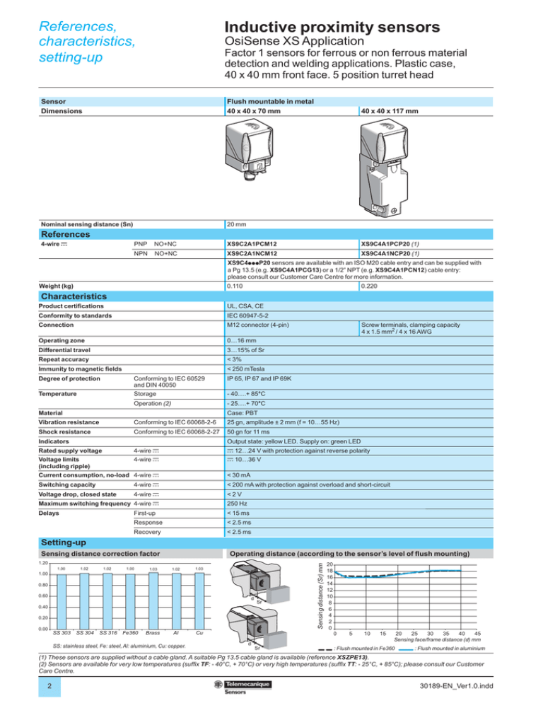
References, characteristics, setting-up 1 Inductive proximity sensors OsiSense XS Application Factor 1 sensors for ferrous or non ferrous material detection and welding applications. Plastic case, 40 x 40 mm front face. 5 position turret head Sensor Dimensions Flush mountable in metal 40 x 40 x 70 mm Nominal sensing distance (Sn) 20 mm 40 x 40 x 117 mm 2 3 References 4-wire c PNP NO+NC XS9C2A1PCM12 XS9C4A1PCP20 (1) NPN NO+NC XS9C2A1NCM12 XS9C4A1NCP20 (1) XS9C4pppP20 sensors are available with an ISO M20 cable entry and can be supplied with a Pg 13.5 (e.g. XS9C4A1PCG13) or a 1/2” NPT (e.g. XS9C4A1PCN12) cable entry: please consult our Customer Care Centre for more information. 4 5 Weight (kg) 0.110 Product certifications UL, CSA, CE Conformity to standards IEC 60947-5-2 Connection M12 connector (4-pin) Operating zone 0…16 mm Differential travel 3…15% of Sr Repeat accuracy < 3% Immunity to magnetic fields 6 Conforming to IEC 60529 and DIN 40050 IP 65, IP 67 and IP 69K Temperature Storage - 40….+ 85°C Operation (2) - 25….+ 70°C Material Case: PBT Vibration resistance Conforming to IEC 60068-2-6 25 gn, amplitude ± 2 mm (f = 10…55 Hz) Shock resistance Conforming to IEC 60068-2-27 50 gn for 11 ms Rated supply voltage 4-wire c c 12…24 V with protection against reverse polarity Voltage limits (including ripple) 4-wire c c 10…36 V Output state: yellow LED. Supply on: green LED Current consumption, no-load 4-wire c 8 Screw terminals, clamping capacity 4 x 1.5 mm2 / 4 x 16 AWG < 250 mTesla Degree of protection Indicators 7 0.220 Characteristics < 30 mA Switching capacity 4-wire c < 200 mA with protection against overload and short-circuit Voltage drop, closed state 4-wire c <2V Maximum switching frequency 4-wire c 250 Hz Delays First-up < 15 ms Response < 2.5 ms Recovery < 2.5 ms Setting-up Operating distance (according to the sensor’s level of flush mounting) 9 1.00 1.02 1.02 1.00 1.03 1.02 1.03 1.00 0.80 0.60 d 0.40 Sr 0.20 10 0.00 SS 303 SS 304 SS 316 Fe360 Brass Al SS: stainless steel, Fe: steel, Al: aluminium, Cu: copper. Cu Sensing distance (Sr) mm Sensing distance correction factor 1.20 20 18 16 14 12 10 8 6 4 2 0 0 d Sr 5 10 15 20 25 30 35 40 45 Sensing face/frame distance (d) mm : Flush mounted in Fe360 : Flush mounted in aluminium (1) These sensors are supplied without a cable gland. A suitable Pg 13.5 cable gland is available (reference XSZPE13). (2) Sensors are available for very low temperatures (suffix TF: - 40°C, + 70°C) or very high temperatures (suffix TT: - 25°C, + 85°C); please consult our Customer Care Centre. 2 30189-EN_Ver1.0.indd Setting-up (continued), schemes, dimensions Inductive proximity sensors OsiSense XS Application Factor 1 sensors for ferrous or non ferrous material detection and welding applications. Plastic case, 40 x 40 mm front face. 5 position turret head Setting-up (continued) Minimum mounting distances (mm) e e Sensors flush mountable in metal 1 e Side by side Face to face Facing a metal object e u 80 e u 200 e u 60 Wiring schemes 4 1 2 4-wire c, NO + NC outputs M12 connector 1: + V 2: NC Output 3: 0 V 4: NO Output 3 2 PNP 1 1 4 (NO) 2 (NC) + 3 – NPN 4 (NO) 2 (NC) + 3 – 3 Accessories Description XSZPSC2 XSZPKC2 Use for Reference Stainless steel rigid protective cover (only suitable for use when detecting from the top) Welding XSZPSC2 Weight kg 0.010 Protective sheet (for sensing face of sensor) Sold in lots of 5 Welding XSZPKC2 0.010 Dimensions Head positions XS9C2A1PCM12 and XS9C2A1NCM12 XS9C2A1PCM12 and XS9C2A1NCM12 40 4 5 72,9 40 44,9 1 2 3 6 2 4 30 40 = = XS9C4A1PCP20 and XS9C4A1NCP20 7 6 5 XS9C4A1PCP20 and XS9C4A1NCP20 40 (1) 8 6 118,3 2 59,9 4 Ø5,45 15,9 41,3 5 45 40 3 = 30 40 1 8 7 = 10 (1) 2 elongated holes Ø 5.3 x 7 mm. Tightening torque of cover fixing screws and clamp screws: < 1.2 N.m / < 10.62 Ib-in. 30189-EN_Ver1.0.indd 9 3


