7420DB0501R04/16
04/2016
Data Bulletin
Replaces 7420DB0501R02/16 02/2016
Power-Dry II™ Dry-Type, Small Power Transformers
225–15,000 kVA Three-Phase, 600 V–35 kV Primary Voltage,
120 V–15 kV Secondary Voltage
Class 7420
Retain for future use.
Introduction
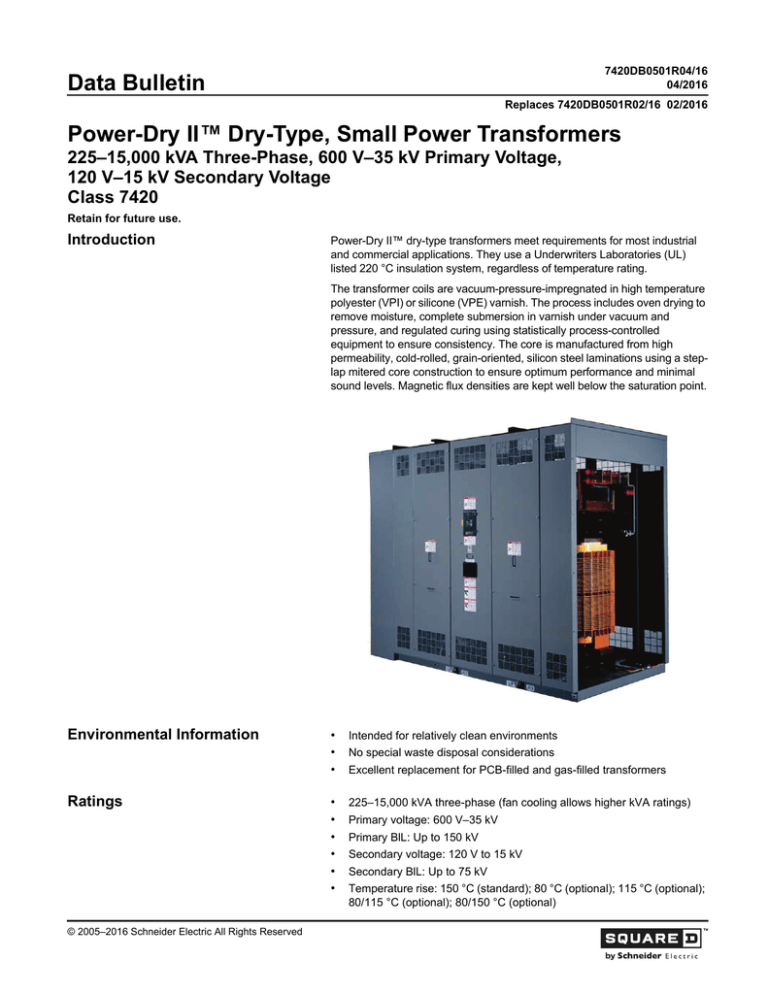
Power-Dry II™ dry-type transformers meet requirements for most industrial
and commercial applications. They use a Underwriters Laboratories (UL)
listed 220 °C insulation system, regardless of temperature rating.
The transformer coils are vacuum-pressure-impregnated in high temperature
polyester (VPI) or silicone (VPE) varnish. The process includes oven drying to
remove moisture, complete submersion in varnish under vacuum and
pressure, and regulated curing using statistically process-controlled
equipment to ensure consistency. The core is manufactured from high
permeability, cold-rolled, grain-oriented, silicon steel laminations using a steplap mitered core construction to ensure optimum performance and minimal
sound levels. Magnetic flux densities are kept well below the saturation point.
Environmental Information
Ratings
© 2005–2016 Schneider Electric All Rights Reserved
•
•
•
Intended for relatively clean environments
•
•
•
•
•
•
225–15,000 kVA three-phase (fan cooling allows higher kVA ratings)
No special waste disposal considerations
Excellent replacement for PCB-filled and gas-filled transformers
Primary voltage: 600 V–35 kV
Primary BlL: Up to 150 kV
Secondary voltage: 120 V to 15 kV
Secondary BlL: Up to 75 kV
Temperature rise: 150 °C (standard); 80 °C (optional); 115 °C (optional);
80/115 °C (optional); 80/150 °C (optional)
Power-Dry II™ Dry-Type, Small Power Transformers
Data Bulletin
Certifications
Special Design Options
Applicable Standards
2
7420DB0501R04/16
04/2016
•
•
•
ISO 9001 registered
•
•
•
•
•
•
•
•
Seismic qualifications
•
IEEE C57.12.01™—Standard General Requirements for Dry-Type
Distribution and Power Transformers Including Those With Solid Cast
and/or Resin-Encapsulated Windings
•
ANSI C57.12.50—Requirements for Ventilated Dry-Type Distribution
Transformers, 1–500 kVA Single-Phase and 15–500 kVA Three-Phase,
with High Voltage 601–34,500 Volts, Low Voltage 120–600 Volts
•
IEEE C57.12.51™—Requirements for Ventilated Dry-Type Power
Transformers, 501 kVA and larger Three-Phase, with High Voltage
601–34,500 Volts, Low Voltage 20BY/120–4,160 Volts
•
ANSI C57.12.55—Conformance Standard for Transformers—Dry-Type
Transformers Used in Unit Installations, Including Unit Substations
•
IEEE C57.12.56™—Standard Test Procedure for Thermal Evaluation of
Insulation Systems for Ventilated Dry-Type Power and Distribution
Transformers
•
IEEE C57.12.58™—Guide for Conducting a Transient Voltage Analysis
of a Dry-Type Transformer Coil
•
IEEE C57.12.59™—Guide for Dry-Type Transformer Through-Fault
Current Duration
•
IEEE C57.12.70™—Terminal Markings and Connections for Distribution
and Power Transformers
•
IEEE C57.12.80™—Standard Terminology for Power and Distribution
Transformers
•
IEEE C57.12.91™—Test Code for Dry-Type Distribution and Power
Transformers
•
IEEE C57.94™—Recommended Practice for Installation, Application,
Operation, and Maintenance of Dry-Type General Purpose Distribution
and Power Transformers
•
IEEE C57.96™—Guide for Loading Dry-Type Distribution and Power
Transformers
UL (standard); CSA (optional)
DOE 2016 Energy Efficient (225–2500 kVA)
Special sound requirements
Low X/R ratios
Higher overload capacity
Special altitude requirements
Retrofit designs
Higher efficiency requirements
Special ambient conditions
© 2005–2016 Schneider Electric All Rights Reserved
7420DB0501R04/16
04/2016
Specifications
Power-Dry II™ Dry-Type, Small Power Transformers
Data Bulletin
A. The transformer(s) shall be the unit substation type with side-mounted
primary and secondary terminations.
B. Primary terminations shall be designed for close coupling to [a metal
enclosed air load break switch section] [a switchgear section] [an air
terminal chamber to be provided with the transformer]. Secondary
terminations shall be designed for close coupling to [a switchgear
section] [a switchboard section] [an air terminal chamber to be provided
with the transformers].
C. Orientation shall be primary on the [left] [right] when facing the
transformer front.
D. The [VPI] [VPE] transformer(s) shall be rated [ ______kVA AA]
[ ______/______kVA AA/FFA] [ ______/ ______kVA AA/FA]. Primary
voltage ______volts delta. Secondary voltage ______volts [wye] [delta],
[3-wire] [4-wire], 60 Hz with two 2½% full-capacity above normal and two
2½% full-capacity below normal primary taps. Impedance shall be [
______%] [manufacturer's standard impedance], ±7½%. All
transformers shall have an average temperature rise of [80] [115] [150]
[80/115] [80/150] °C above a 40 °C maximum, 30 °C average ambient.
E. The basic impulse levels (BIL) shall be a minimum of [60 kV for the
15 kV class] [optional 95 kV BIL available] [10 kV for the 1.2 kV class].
Primary and secondary BIL shall be ______kV and ______kV
respectively.
F. The coils and all clamping structures shall be assembled on the core,
and then dried at atmospheric pressure in an oven through which hot air
is continuously circulated. The totally assembled core and coil assembly
shall be vacuum pressure impregnated in varnish. The varnish shall be
cured on the core and coil assembly following an established
temperature versus time baking cycle in a hot air circulating oven. The
process shall effectively impregnate the entire core and coil assembly
which results in a unit which is virtually impermeable to moisture, dust,
dirt, salt air, and other industrial contaminants.
G. The coils shall be wound with [aluminum] [copper] conductors.
H. All insulating materials are to be in accordance with IEEE C57.12.01™
for 220 °C UL insulation system.
I.
All cores to be constructed of high grade, grain-oriented, non-aging
silicon steel with high magnetic permeability, and low hysteresis and
eddy current losses. Magnetic flux densities are to be kept well below
the saturation point. Core lamination shall be miter cut at the core
corners to reduce hot spots, core loss, excitation current, and sound
level. The laminations shall be clamped together using insulated bolts
through the core laminations to provide proper pressure throughout the
length of the core.
J. The transformer enclosures shall be ventilated [indoor] [outdoor] and
fabricated of heavy gauge, sheet steel construction. Enclosures are to be
provided with lifting devices bolted or welded to the base structure and
shall have jacking pads designed to be flush with the enclosure. The base
is to be constructed of structural steel members to permit skidding or
rolling in any direction. There shall be no metal-to-metal contact. Rubber
vibration isolation pads shall be installed by the manufacturer between the
core and coil and the enclosure. The core shall be visibly grounded to the
ground bus or ground pad by means of a flexible grounding conductor
sized in accordance with applicable UL and NEC® standards.
K. The enclosure shall be constructed of heavy gauge sheet steel and shall
be finished with [ANSI 49] [ANSI 61] paint color. The paint shall be
applied using an electrostatically deposited dry powder paint system. All
© 2005–2016 Schneider Electric All Rights Reserved
3
Power-Dry II™ Dry-Type, Small Power Transformers
Data Bulletin
7420DB0501R04/16
04/2016
ventilating openings shall be in accordance with NEMA and the NEC
standards for ventilated enclosures.
L. Transformer sound levels shall be warranted by the manufacturer not to
exceed the values specified in IEEE C57.12.01™.
M. The transformer(s) shall be provided [with lightning arresters] [without
lightning arresters]. If provided, metal-oxide, gapless-type distribution
class lightning arresters shall be installed by the manufacturer on the
high voltage side of the transformer to provide additional protection
against high voltage lightning or switching surges.
N. The transformer(s) shall be designed for use [without fans] [with fans to
increase the kVA capacity by 33%]. If provided, fan cooling equipment
shall include an electronic-winding temperature monitor controlled
automatically by a Type K thermocouple placed in the low voltage air duct.
The temperature monitor must contain yellow and red indicating lights.
The yellow and red lamps signal that fan and alarm contacts have been
activated. Alarm contacts shall be provided for fans, alarm, and trip
function. An audible alarm must sound when the highest phase
temperature exceeds a preset point. The fans must be able to operate in
either manual or automatic mode. A minimum of six fans shall be provided
and shall be controlled automatically by the sensor in the low voltage air
duct. The forced air cooling system shall include: fans, control wiring,
controller with test switch, current limiting fuses in the power supply to the
controller, indication lights, alarm silencing relay, auto/manual switch, and
necessary accessories to properly control the system.
O. Testing shall be conducted in accordance with IEEE C57.12.91™ and
shall include, at a minimum, the following tests:
1. Ratio
2. Polarity
3. Phase rotation
4. No-load loss
5. Excitation current
6. Impedance voltage
7. Load loss
8. Applied potential
9. Induced potential
10. Quality control impulse
11. Temperature (typical data from previous unit is acceptable)
12. Sound (typical data from previous unit is acceptable)
4
© 2005–2016 Schneider Electric All Rights Reserved
7420DB0501R04/16
04/2016
Technical Data
Power-Dry II™ Dry-Type, Small Power Transformers
Data Bulletin
Table 1:
Standard Transformer Ratings, Primary Voltage Class
2.3–46 kV, 150 °C Rise, 30 °C Ambient
kVA 3-Phase
Fan-Cooled
Self-Cooled Ventilated
Dry
Secondary Voltage
Fan-Cooled
4160Y/2400 V
Weather
208Y/120 V 480Y/277 V
4160 V Delta
Resistant 240 V Delta 480 V Delta
2400 V Delta
Ventilated
225
300
300
X
X
X
300
400
400
X
X
X
500
667
667
X
X
X
750
1000
1000
X
X
X
1000
1333
1333
X
X
X
1500
2000
2000
X
X
X
2000
2666
2666
X
X
2500
3333
3333
X
X
3750
4687
4687
X
5000
6250
6250
X
7500
9375
9375
X
10000
12000
12000
X
The above combinations are based on standard designs. Other than standard
designs may place further restrictions on the availability of voltage and kVA
combinations. Consult the factory for final determination.
Table 2:
Altitude Derating Factor 1
Altitude (FT)
1
© 2005–2016 Schneider Electric All Rights Reserved
kVA Correction
VPI (AA)
Forced Air (FA)
BIL Correction
3300
1.00
1.00
1.00
4000
0.994
0.989
0.98
5000
0.985
0.974
0.95
6000
0.975
0.959
0.92
7000
0.966
0.944
0.89
8000
0.957
0.929
0.86
9000
0.948
0.914
0.83
10,000
0.939
0.898
0.80
11,000
0.930
0.883
0.77
12,000
0.921
0.868
0.75
13,000
0.912
0.853
0.72
14000
0.903
0.838
0.70
15,000
0.894
0.823
0.67
3.28 feet = 1 meter
5
Power-Dry II™ Dry-Type, Small Power Transformers
Data Bulletin
7420DB0501R04/16
04/2016
Table 3:
Audible Sound Levels
Self-Cooled
Equivalent
Two-Winding
kVA
Forced Air-Cooled
Equivalent
Two-Winding
kVA
Class AA Rating
Class FA/AFA
Rating
0–9
40
0–1167
67
10–50
45
1168–1667
68
51–150
50
1668–2000
69
151– 300
55
2001–3333
71
301–500
60
3334–5000
73
501–700
62
5001–6667
74
701–1000
64
6668–8333
75
1001–1500
65
8334–10000
78
1501–2000
66
10001–13333
82
2001–3000
68
3001–4000
70
4001–5000
71
5001–6000
72
6001–7500
75
7501–10000
79
10001–15000
82
Table 4:
System Voltages and Transformer BIL Ratings
Nominal L-L
System Voltages
(kV)
Standard and Optional Transformer BIL Ratings
10
20
30
0.25
Non
e
0.6
S
1
1
1.2
S
1
1
2.5
5.0
8.7
15.0
S
45
1
1
S
1
S
60
95
110
125
150
1
1
S
1
1
1
18.0
S
1
1
25.0
2
S
1
1
2
S
34.5
200
1
S = Standard value.
1 = Optional higher levels where exposure to overvoltage occurs and improved
protective margins are required.
2 = Lower levels where protective characteristics of applied surge arresters have
been evaluated and found to provide appropriate surge protection.
6
© 2005–2016 Schneider Electric All Rights Reserved
7420DB0501R04/16
04/2016
Table 5:
Power-Dry II™ Dry-Type, Small Power Transformers
Data Bulletin
Performance Data
Typical Performance Data
kVA
%IZ
%IR
%IX
X/R Ratio
1.0 PF
0.9 PF
0.8 PF
0.7 PF
225
4.50
1.92
4.07
2.12
2.00
3.54
4.00
4.26
300
4.50
1.74
4.15
2.38
1.83
3.42
3.41
4.20
500
5.50
1.57
5.27
3.36
1.71
3.79
4.47
4.90
750
5.75
1.38
5.58
4.05
1.53
3.77
4.52
4.99
1000
5.75
1.31
5.60
4.28
1.47
3.72
4.47
4.96
1500
5.75
1.15
5.63
4.89
1.31
3.60
4.37
4.88
2000
5.75
1.05
5.65
5.40
1.21
3.51
4.31
4.82
2500
5.75
1.01
5.66
5.60
1.17
3.49
4.28
4.80
3000
5.75
1.07
5.65
5.28
1.29
3.58
4.36
4.87
3750
5.75
0.99
5.66
5.72
1.15
3.47
4.27
4.79
5000
5.50
0.80
5.44
6.80
0.95
3.20
3.98
4.50
Table 6:
kVA
1
Regulation
Typical Performance Data: High Voltage—15 kV Class; Low Voltage—600 V Class
No Load
Losses (Watts)
Full Load
Losses 1
(Watts)
Total Losses
(Watts)
Efficiency 1
133%
125%
100%
75%
50%1
25%
225
800
3300
4100
97.83
97.93
98.21
98.45
98.75
98.24
300
1000
4000
5000
98.02
98.10
98.36
98.58
98.84
98.36
500
1200
6400
7600
98.15
98.24
98.50
98.74
99.04
98.74
750
1750
8200
9950
98.40
98.47
98.69
98.88
99.13
98.81
1000
2400
8300
10700
98.73
98.79
98.94
99.07
99.21
98.85
1500
2900
11000
13900
98.89
98.94
99.08
99.20
99.34
99.05
2000
3500
12800
16300
99.03
99.07
99.19
99.29
99.41
99.15
2500
3650
17000
20650
99.00
99.04
98.18
99.30
99.45
99.25
3000
7500
34000
41500
98.33
98.41
98.64
98.83
98.94
98.73
3750
9500
37000
46500
98.52
98.58
98.78
98.93
99.01
98.76
5000
11500
40000
51500
98.78
98.83
98.98
99.10
99.15
98.89
Full load losses and efficiencies are at a reference temperature of 170 °C in accordance with IEEE Standard C57.12.91. The efficiencies of
transformers with a 225–2,500 kVA rating at 50% load are at a reference temperature of 75 °C in accordance with DOE Test Procedure 10 CFR,
Part 431, Subpart K, Appendix A.
© 2005–2016 Schneider Electric All Rights Reserved
7
Power-Dry II™ Dry-Type, Small Power Transformers
Data Bulletin
7420DB0501R04/16
04/2016
Table 7:
Standard % Impedance
High Voltage BIL (kV)
Percent Impedance
95 and below
5.75
Above 95
7
Table 8:
Standard Enclosure Design Dimension and Weights 1,2
Dimensions (inches)
kVA
Loading
ANSI/IEEE Loading Guide
Weight (lbs)
Height
Width
Depth
225
94.0
84.0
54.0
300
94.0
84.0
54.0
4600
500
100.0
84.0
60.0
5039
4200
750
100.0
84.0
60.0
6219
1000
100.0
84.0
60.0
7267
1500
100.0
96.0
60.0
9374
2000
100.0
96.0
60.0
11400
2500
100.0
102.0
60.0
15700
3000
100.0
108.0
60.0
13500
3750
100.0
108.0
60.0
16000
5000
124.0
144.0
66.0
25000
1
Values listed are typical and should not be used for construction purposes.
2
Dimensions are based on standard BIL and 150 °C temperature rise.
Power-Dry II transformers are designed to operate at rated load with rated
voltage and frequency applied in “usual service” conditions. It is possible to
carry overloads without loss of life expectancy. The following table shows
the permissible overloads that may be carried without loss of transformer life
expectancy only if occurring once in any 24-hour period given a 150 °C rise
transformer in a 30 °C ambient.
Table 9:
Daily Loads Above Rating to Give Normal Life Expectancy
Transformer Load Before and After Overload
Peak Load
Time in Hours
90%
70%
50%
0.5
1.33
1.43
1.49
1
1.21
1.25
1.28
2
1.14
1.15
1.16
4
1.09
1.10
1.10
8
1.05
1.06
1.06
Example 1: A 1000 kVA transformer loaded at 90% (900 kVA) could be
loaded up to 1330 kVA for 30 minutes without loss of transformer life if
loading returns to 900 kVA or less after the overload.
Example 2: A 1000 kVA transformer loaded at 50% (500 kVA) could be
loaded up to 1280 kVA for 60 minutes without loss of transformer life if
loading returns to 500 kVA or less after the overload.
8
© 2005–2016 Schneider Electric All Rights Reserved
7420DB0501R04/16
04/2016
Heat Contribution
Power-Dry II™ Dry-Type, Small Power Transformers
Data Bulletin
Heat contribution is the heat a transformer may contribute to its
environment. This may represent additional air conditioning burden in
summer months, or may be used in calculating heating requirements during
winter months. This heat is the result of transformer losses and is a function,
in part, of loading. The following table demonstrates the effect of loading on
heat contribution.
Table 10:
kVA
225
300
500
750
1000
1500
© 2005–2016 Schneider Electric All Rights Reserved
Typical Heat Contribution: High Voltage—15 kV Class;
Low Voltage—480Y/277 V
% Load
BTU/Hour
kVA
% Load
BTU/Hour
25
3436
25
14685
50
5549
50
22881
75
9071
100
14002
75
36541
100
55665
125
133
20341
125
80253
22666
133
89275
25
4269
25
16093
50
6830
50
26979
75
11099
100
17075
125
133
2000
75
45121
100
70520
24759
125
103176
27578
133
115158
2500
25
5464
25
32869
50
9562
50
54640
75
16392
100
25954
75
90924
100
141723
125
133
38248
125
207034
42759
133
230999
25
7726
25
40340
50
12977
50
64031
75
21728
100
33979
125
133
3000
75
103517
100
158798
49731
125
229872
55511
133
255952
3750
25
9968
25
47810
50
15282
50
73423
75
24140
100
36541
75
116110
100
175873
125
133
52484
125
252710
58335
133
25
12251
280904
50
19295
75
31034
100
47469
125
68599
133
76352
5000
9
Power-Dry II™ Dry-Type, Small Power Transformers
Data Bulletin
Schneider Electric USA, Inc.
800 Federal Street
Andover, MA 01810 USA
888-778-2733
www.schneider-electric.us
10
7420DB0501R04/16
04/2016
Electrical equipment should be installed, operated, serviced, and maintained only by
qualified personnel. No responsibility is assumed by Schneider Electric for any
consequences arising out of the use of this material.
Power-Dry II, Schneider Electric, and Square D are trademarks and the property of
Schneider Electric SE, its subsidiaries, and affiliated companies. All other trademarks
are the property of their respective owners.
© 2005–2016 Schneider Electric All Rights Reserved

