DF-52400:A
5600 (A) Series
Mechanical Heat Detectors
Conventional Initiating Devices
GENERAL
System Sensor’s 5600 Series mechanical heat detectors offer
property protection against fire and for non-life-safety installations, where smoke detectors are inappropriate.
Multiple configurations. The 5600 Series offers a full line of
configurations to accommodate a broad range of applications.
Both single- and dual-circuit models are offered, each available for low- and high-temperature ratings with either fixedtemperature or combination fixed-temperature/rate-of-rise
(ROR) activation. The ROR element of the fixed/ROR models
is restorable, to accommodate field-testing the unit.
Installation flexibility. To satisfy a variety of installations, the
5600 Series easily mounts to single-gang and octagonal backboxes. These models also accommodate 4" (101.6 mm)
square backboxes when used with a plastic ring. The mounting
bracket is reversible to allow for flush- and surface-mount
backbox installations.
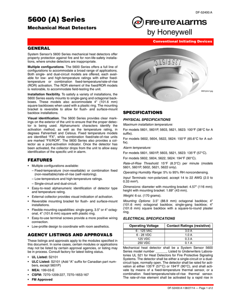
Visual identification. The 5600 Series provides clear markings on the exterior of the unit to ensure that the proper detector is being used. Alphanumeric characters identify the
activation method, as well as the temperature rating, in
degrees Fahrenheit and Celsius. Fixed temperature models
are identified “FX”, while combination fixed/rate-of-rise units
are marked “FX/ROR”. The 5600 Series also provides a collector as a post-activation indicator. Once the detector has
been activated, the collector drops from the unit to allow easy
identification of the specific unit in alarm.
FEATURES
• Multiple configurations available:
– Fixed-temperature (non-resettable) or combination fixed
(non-resettable)/rate-of-rise (self-restoring).
– Low-temperature and high-temperature ratings.
– Single-circuit and dual-circuit.
• Easy-to-read alphanumeric identification of detector type
and temperature rating.
• External collector provides visual indication of activation.
• Reversible mounting bracket for flush- and surface-mount
installations.
• Flexible mounting capabilities: single-gang, 3.5" or 4" octagonal, 4" (101.6 mm) square with plastic ring.
• Easy-to-use terminal screws provide a more positive wiring
connection.
• Low-profile design to coordinate with room aesthetics.
AGENCY LISTINGS AND APPROVALS
These listings and approvals apply to the modules specified in
this document. In some cases, certain modules or applications
may not be listed by certain approval agencies, or listing may
be in process. Consult factory for latest listing status.
• UL Listed: S2101
• ULC Listed: S2101 (Add “A” suffix for Canadian part numbers, except 5601P)
• MEA: 199-03-E
• CSFM: 7270-1209:227, 7270-1653:167
• FM Approved
6931pho1.jpg
SPECIFICATIONS
PHYSICAL SPECIFICATIONS
Maximum installation temperature:
For models 5601, 5601P, 5603, 5621, 5623: 100°F (38°C for A
suffix).
For models 5602, 5604, 5622, 5624: 150°F (65.6°C for A suffix).
Alarm temperature:
For models 5601, 5601P, 5603, 5621, 5623: 135°F (57°C).
For models 5602, 5604, 5622, 5624: 194°F (90°C).
Rate-of-Rise Threshold: 15°F (8.3°C) per minute (models
5601, 5601P, 5602, 5621, 5622 only).
Operating Humidity Range: 5% to 95% RH noncondensing.
Input Terminals: non-polarized, accept 14 to 22 AWG (2.0 to
0.33 mm²).
Dimensions: diameter with mounting bracket: 4.57" (116 mm);
height with mounting bracket: 1.69" (43 mm).
Weight: 6 oz. (170 grams).
Mounting Options: 3.5" (88.9 mm) octagonal backbox; 4"
(101.6 mm) octagonal backbox; single-gang backbox; 4"
(101.6 mm) square backbox with a square-to-round plaster
ring.
ELECTRICAL SPECIFICATIONS
Operating Voltage
Contact Ratings (resistive)
6 - 125 VAC
6 - 28 VDC
125 VDC
250 VDC
3.0 A
1.0 A
0.3 A
0.1 A
Mechanical heat detector shall be a System Sensor 5600
Series model number ______, Listed to Underwriters Laboratories UL 521 for Heat Detectors for Fire Protective Signaling
Systems. The detector shall be either a single-circuit or a dualcircuit type, normally open. The detector shall be rated for activation at either 135°F (57°C) or 194°F (90°C), and shall activate by means of a fixed-temperature thermal sensor, or a
combination fixed-temperature/rate-of-rise thermal sensor.
The rate-of-rise element shall be activated by a rapid rise in
DF-52400:A • 08/27/14 — Page 1 of 2
temperature, approximately 15°F (8.3°C) per minute. The
detector shall include a reversible mounting bracket for mounting to 3.5-inch (88.9 mm) octagonal, 4-inch (101.6 mm) octagonal, single gang, and 4-inch (101.6 mm) square backboxes
with a square-to-round plastic ring. Wiring connections shall
be made by means of SEMS screws that shall accommodate
14 – 22 AWG wire. The detector shall contain alphanumeric
markings on the exterior of the housing to identify its temperature rating and activation method. The rate-of-rise element of
combination fixed-temperature/rate-of-rise models shall be
restorable, to allow for field-testing. The detectors shall include
an external collector that shall drop upon activation to identify
the unit in alarm.
ORDERING INFORMATION
Model*
Identification
Temperature
Method on Circuit
Rating
Exterior
Activation
UL Protected Spacing,
10’ (3.048 m) Ceiling*
5601P
None
Single 135°F (57°C) Fixed-Temperature/Rate-of-Rise
50 ft. x 50 ft. (15.24 m x 15.24 m)
5601A
None
Single 135°F (57°C) Fixed-Temperature/Rate-of-Rise
50 ft. x 50 ft. (15.24 m x 15.24 m)
5602
Lettering
Single 194°F (90°C) Fixed-Temperature/Rate-of-Rise
50 ft. x 50 ft. (15.24 m x 15.24 m)
5603
Lettering
Single 135°F (57°C) Fixed-Temperature
25 ft. x 25 ft. (7.62 m x 7.62 m)
5604
Lettering
Single 194°F (90°C) Fixed-Temperature
25 ft. x 25 ft. (7.62 m x 7.62 m)
5621
Lettering
Dual
135°F (57°C) Fixed-Temperature/Rate-of-Rise
50 ft. x 50 ft. (15.24 m x 15.24 m)
5622
Lettering
Dual
194°F (90°C) Fixed-Temperature/Rate-of-Rise
50 ft. x 50 ft. (15.24 m x 15.24 m)
5623
Lettering
Dual
135°F (57°C) Fixed-Temperature
25 ft. x 25 ft. (7.62 m x 7.62 m)
5624
Lettering
Dual
194°F (90°C) Fixed-Temperature
25 ft. x 25 ft. (7.62 m x 7.62 m)
NOTE: Refer to NFPA 72 guidelines for spacing reductions when ceiling heights exceed 10 feet (3.048 m).
* Add an “A” to part number for ULC model.
WIRING DIAGRAMS
Single-Circuit Models
Dual-Circuit Models
6931wir1.wmf
6931wir2.wmf
©2014 by Honeywell International Inc. All rights reserved. Unauthorized use
of this document is strictly prohibited.
This document is not intended to be used for installation purposes.
We try to keep our product information up-to-date and accurate.
We cannot cover all specific applications or anticipate all requirements.
All specifications are subject to change without notice.
For more information, contact Fire•Lite Alarms. Phone: (800) 627-3473, FAX: (877) 699-4105.
www.firelite.com
Page 2 of 2 — DF-52400:A • 08/27/14


