ohm`s law with batteries
advertisement

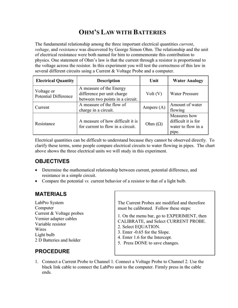
OHM’S LAW WITH BATTERIES The fundamental relationship among the three important electrical quantities current, voltage, and resistance was discovered by George Simon Ohm. The relationship and the unit of electrical resistance were both named for him to commemorate this contribution to physics. One statement of Ohm’s law is that the current through a resistor is proportional to the voltage across the resistor. In this experiment you will test the correctness of this law in several different circuits using a Current & Voltage Probe and a computer. Electrical Quantity Voltage or Potential Difference Current Resistance Description A measure of the Energy difference per unit charge between two points in a circuit. A measure of the flow of charge in a circuit. A measure of how difficult it is for current to flow in a circuit. Unit Volt (V) Ampere (A) Ohm () Water Analogy Water Pressure Amount of water flowing Measures how difficult it is for water to flow in a pipe. Electrical quantities can be difficult to understand because they cannot be observed directly. To clarify these terms, some people compare electrical circuits to water flowing in pipes. The chart above shows the three electrical units we will study in this experiment. OBJECTIVES Determine the mathematical relationship between current, potential difference, and resistance in a simple circuit. Compare the potential vs. current behavior of a resistor to that of a light bulb. MATERIALS LabPro System Computer Current & Voltage probes Vernier adapter cables Variable resistor Wires Light bulb 2 D Batteries and holder The Current Probes are modified and therefore must be calibrated. Follow these steps: 1. On the menu bar, go to EXPERIMENT, then CALIBRATE, and Select CURRENT PROBE. 2. Select EQUATION. 3. Enter -0.65 for the Slope. 4. Enter 1.6 for the Intercept. 5. Press DONE to save changes. PROCEDURE 1. Connect a Current Probe to Channel 1. Connect a Voltage Probe to Channel 2. Use the black link cable to connect the LabPro unit to the computer. Firmly press in the cable ends. 2. 3. 4. 5. 6. Plug in the LabPro unit using the power adapter. Open up the Logger Pro or Logger Lite software. Using the folder icon, open the experiment called “Ohm’s Law”. You can search for it. Calibrate the current sensor (see box on front page). Setup the circuit as demonstrated with the variable resistor wiper set in the middle. The Voltage Probe should be in parallel and the Current Probe in series with the positive end closer to the positive terminal of the battery (red wire). Note: Do not connect the battery until you are ready to take a reading. 7. Press COLLECT. When ready to record the value of the voltage and current press KEEP. When done, store the latest run. 8. Hook up the circuit with only one battery and repeat. 9. Divide the volts by the current and record in the proper column in your data table. 10. Use the ANALYZE menu to do a LINEAR FIT. Click and drag the brackets to select your points. Read the slope of the line (the slope will be resistance or V/I and is “m”). 11. Repeat these steps using a light bulb instead of the variable resistor. DATA TABLES Resistor Voltage (volts) Current (amps) Voltage Current 1D cell 2D cells Light bulb Voltage (volts) Current (amps) Voltage Current 1D cell 2D cells ANALYSIS 1. Compare the values of the resistances for one and two batteries. Are they the same? Does this match the resistance found using the slope of the linear fit? 2. Does your resistor follow Ohm’s law? Base your answer on your experimental data. 3. Does your light bulb follow Ohm’s law? Base your answer on your experimental data. 4. Why do you think the resistance of the light bulb changed?


