Coparison of measured and calculated value of mutual inductance
advertisement
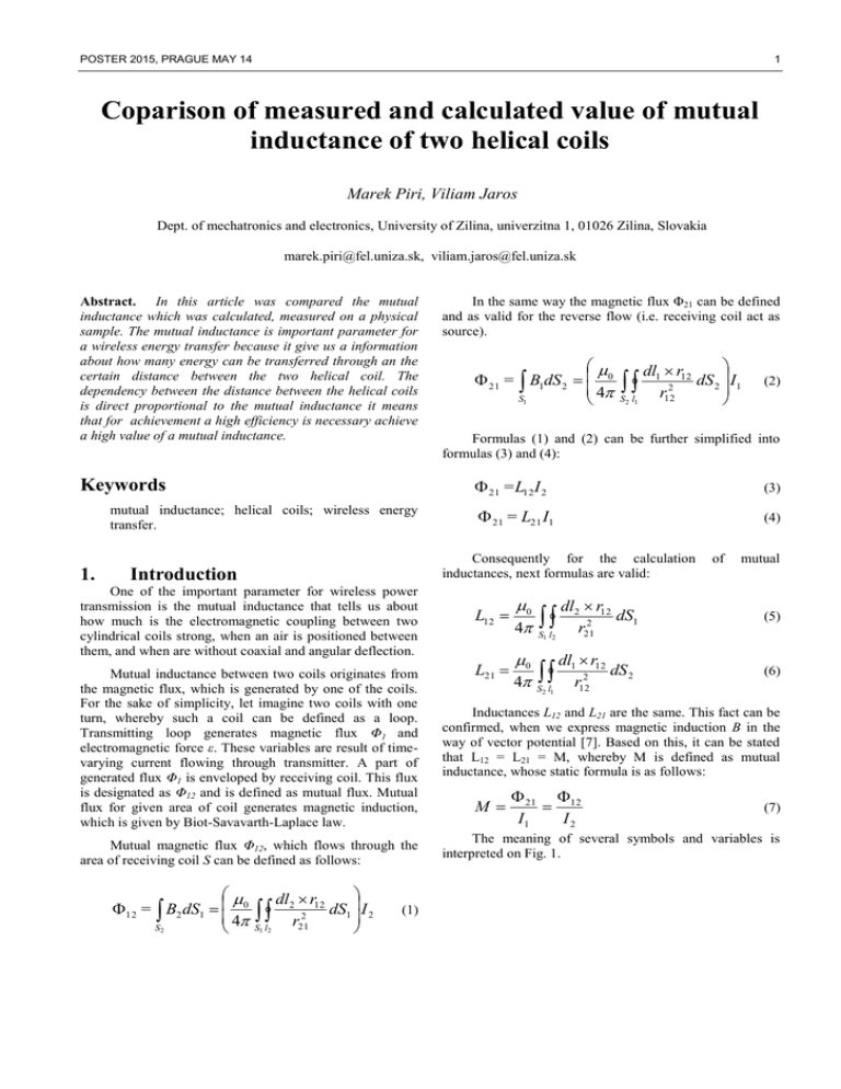
POSTER 2015, PRAGUE MAY 14 1 Coparison of measured and calculated value of mutual inductance of two helical coils Marek Piri, Viliam Jaros Dept. of mechatronics and electronics, University of Zilina, univerzitna 1, 01026 Zilina, Slovakia marek.piri@fel.uniza.sk, viliam.jaros@fel.uniza.sk Abstract. In this article was compared the mutual inductance which was calculated, measured on a physical sample. The mutual inductance is important parameter for a wireless energy transfer because it give us a information about how many energy can be transferred through an the certain distance between the two helical coil. The dependency between the distance between the helical coils is direct proportional to the mutual inductance it means that for achievement a high efficiency is necessary achieve a high value of a mutual inductance. Keywords mutual inductance; helical coils; wireless energy transfer. 1. In the same way the magnetic flux Φ21 can be defined and as valid for the reverse flow (i.e. receiving coil act as source). 21 = B1dS 2 0 4 S1 dl1 r12 dS 2 I1 S l r122 2 1 Formulas (1) and (2) can be further simplified into formulas (3) and (4): 21 =L12 I 2 (3) 21 = L21 I1 (4) Consequently for the calculation inductances, next formulas are valid: Introduction One of the important parameter for wireless power transmission is the mutual inductance that tells us about how much is the electromagnetic coupling between two cylindrical coils strong, when an air is positioned between them, and when are without coaxial and angular deflection. (2) L12 L21 0 4 0 4 S1 l2 dl2 r12 dS1 r212 dl1 r12 dS 2 r122 S 2 l1 of mutual (5) (6) Mutual inductance between two coils originates from the magnetic flux, which is generated by one of the coils. For the sake of simplicity, let imagine two coils with one turn, whereby such a coil can be defined as a loop. Transmitting loop generates magnetic flux Φ1 and electromagnetic force ε. These variables are result of timevarying current flowing through transmitter. A part of generated flux Φ1 is enveloped by receiving coil. This flux is designated as Φ12 and is defined as mutual flux. Mutual flux for given area of coil generates magnetic induction, which is given by Biot-Savavarth-Laplace law. Inductances L12 and L21 are the same. This fact can be confirmed, when we express magnetic induction B in the way of vector potential [7]. Based on this, it can be stated that L12 = L21 = M, whereby M is defined as mutual inductance, whose static formula is as follows: Mutual magnetic flux Φ12, which flows through the area of receiving coil S can be defined as follows: The meaning of several symbols and variables is interpreted on Fig. 1. 12 = B2 dS1 0 4 S2 dl2 r12 dS 1 I2 2 r 21 S1 l2 (1) M 21 12 I1 I2 (7) 2 F. S. MAREK PIRI, S. S. VILIAM JAROS, COMPARISION OF MEASURED AND CALCULATED VALUE OF MUTUAL INDUCTANCE OF TWO HELICAL COILS We can define Magnetic flux for two coaxial round thin coils as integral of the magnetic flux for two wires over whole height of the first coil, while elementary part of coil on the position z’ <z11,z12> (fig. 3) has number of turns: N1 dz´ . h1 Fig. 1. Mutual magnetic coupling of two closed loop. 2. (12) Then it integrate over whole height of the second coil, while elementary part of coil on the position z <z21,z22> has number of turns: Mathematical calculation N2 dz . h2 The first step before mathematical calculation has been verified was development of source code in Matlab. This code serves for computation of self-inductance, and mutual inductances. Main parameters of coils were taken over from existing system for wireless energy transfer. (13) For calculation of the magnetic flux for round coil use of vector’s potential A is better choice, instead of magnetic induction B. Vector’s potential is defined by B rotA (8) Then magnetic flux can be defined by integration of the vector’s potential along circumference of the current turn. A.dl (9) l Advantage of using vector’s potential is that, we can work with it’s as a scalar quantity, for a coaxial arrangement of the round coils. Vector’s potential driven by thin current turn can be written as A (r , , z ) 0 I 2 4 0 cos ´ r R cos ´( z z´)2 2 2 1 d´ (10) Fig. 3. Vector´s potential for two round wire Magnetic flux for two coaxial thin round coils can by written as: For better explanation of (10), see [1]. Magnetic flux of two round wires are shown in (fig. 2), and can by written as: 2 I w / w 0 R1 R2 0 2 cos ´ R12 R22 2R1 R2 cos ´( z z´)2 (14) d´ (11) Mutual inductance for two coaxial, thin, round coil can be defined by substituting (14) to the (7) (15) This expression can be rewritten by elliptical integrals as: Fig. 2. Vector´s potential for two round wire POSTER 2015, PRAGUE MAY 14 3 lim ( (16) Where function X(k) is defined as: 1 1 k2 3 4 X (k ) [ 2 ( K (k ) E (k )) k k 2 2 3 k 2 E (k ) (1 k ) 2 ( , k )] 2 2 2 4 R1 R2 4 R1 R2 2 2 2 ( R1 R2 ) ( z 22 z11) ( R1 R2 ) 2 d11 k 22 4 R1 R2 4 R1 R2 2 2 2 ( R1 R2 ) ( z 22 z12 ) ( R1 R2 ) 2 d 22 k33 (17) d 22 d 33 0 k 22 k33 1 (23) 1 k 2 ( K (k ) E (k )) 0 1 k 2 (24) lim 3 4 3 4 E (k ) 1 1 2 2 lim (25) For function X (k11) and X (k44) we can write X (k11 ) X (k 44 ) X (k ) 1 1 k 2 ( K (k ) E (k )) E (k ) 2 k k (26) Because z 22 z11 z 21 z12 h (18) 4 R1 R2 4 R1 R2 2 2 2 ( R1 R2 ) ( z21 z11) ( R1 R2 ) 2 d 33 k11 k 44 k 4 R1 R2 ( R1 R2 ) 2 h 2 (27) When substituting (22) and (26) to (16), then we can write self - inductance as 4 R1 R2 4 R1 R2 k 44 2 2 2 ( R1 R2 ) ( z 21 z12 ) ( R1 R2 ) 2 d 33 8 N 2 1 1 k 2 LC / C 0 R 3 2 2 ( K (k ) E (k ) E (k )) 1 (28) 3 h k k Axial distance in (18) is: h1 h2 2 2 h h z 22 z12 d 22 d 1 2 2 2 h1 h2 z 21 z11 d 33 d 2 2 h1 h2 z 21 z12 d 44 d 2 2 (22) Function X (k22) and X (k33) from (16) are equal to 1 because: Where K (k) is elliptical integral of first kind, E (k) is elliptical integral of second kind and Π (n, k) is elliptical integral of third kind. Elliptical integrals are explained in next section. Variable n is known as elliptical characteristic and k is module of the elliptical integrals [2]. Modules of the elliptical integrals for two thin, round coil are defined as: k11 k 2 2 ,k) 0 . 2 z 22 z11 d11 d 3. (19) /2 Elliptic integral of third kind is for this parameter ρ 0 (20) d 1 k 2 sin 2 (29) Substitution t = sin φ we get a normalized form: 1 K (k ) 0 If we can determine expression for self – inductance, we can use expression (16), but distance between middles of the coils is equal zero. In this case radius R1 and R2 are same. Parameter ρ is there determined as R1 R2 2 . Absolute elliptic integral first kind is defined as: K (k ) , where d is distance between middles of the coils. Parameter ρ (rx, xy) gives relative values of the radius of round coils. Parameter ρ in this case is: ( R .R ) 2 ( R1.R2 ) 1 2 2 R1 R2 Elliptic integrals dt 1 t 2 1 k 2t 2 (30) For k <0,1> has this integral real values and for limit values of k is: K (0) = π/2, K (1) →∞ (21) Absolute elliptic integral second kind is defined as (31) 4 F. S. MAREK PIRI, S. S. VILIAM JAROS, COMPARISION OF MEASURED AND CALCULATED VALUE OF MUTUAL INDUCTANCE OF TWO HELICAL COILS /2 E (k ) 1 k 2 sin 2 d (32) 0 Substitution t = sin φ we get a normalized form 1 E (k ) 0 1 k 2t 2 dt 1 t2 (33) And E (0) = π/2, E (1) →∞ (34) Absolute elliptic integral of the third kind is defined as: /2 (n, k ) 0 1 1 n sin 2 1 k 2 sin 2 d (35) Substitution t = sin φ we get a normalized form 1 (k ) 0 1 (1 nt 2 ) (1 t 2 )(1 k 2t 2 ) In this subsystem interpreted matlab function blocks are used, where elliptic integrals by function mfun are defined [3] - [5]. With this block, program can calculate absolute elliptic integrals of first, second and third kind. This subsystem calculates value of self – inductance by using (28) and value of the self-inductance of coils is displayed at display block. Third part is similar as second, but this part is for calculation of the mutual inductance of two wire coils. There at first parameter ρ by using (20) are calculated, axial distances d11, d22, d33, d44 by using (19) and modules of elliptical integrals k11, k22, k33, k44 by using (18). Then in next subsystem mutual inductance by using (16) is calculated and value of the mutual inductance of coils are displayed at display block. dt (36) and (n , k ) 0, (n 0, k ) K (k ) (n 1, k ) 0 M [uH] 100 1.6247 120 1.1949 140 0.899 160 0.6891 180 0.537 Tab. 1. Calculated mutual inductance in Matlab. (37) 4. Program for calculation mutual and self inductance Program for calculation of self - inductance and mutual inductance of two air coils is written in Matlab/ Simulink. This can be divided to three parts (fig. 4). First part is part, where we define main parameters of both coils e.g. radius or height of coil. Main parameters of coils were taken over from existing system for wireless energy transfer. Second part is calculation of self – inductance. At first, the program calculates module the elliptic integrals and then next subsystem calculates self – inductance. Fig. 4. GUI for calculation of the mutual and self inductance distance [mm] 5. Experimental verification on a physical sample As was already mentioned, the main parameters of the coils were taken over from existing system for wireless energy transfer. The transmitting and receiving coils were designed with helical geometry, whereby coil former was prepared from cardboard paper. In this way, the proper shape and turn’s spacing were secured. As high frequency generator the evaluation board EPC9003 (fig. 5) has been used [6]. Its main specification is the use of perspective GaN power transistor devices (eGaN EPC2010C) which are suitable for very high frequency operation. This evaluation board also contains necessary equipment for driving these power devices and for sensing required electrical variables in the power circuit. POSTER 2015, PRAGUE MAY 14 5 After coil construction, the main parameters influencing power transfer have been measured (selfinductance, parasitic resistance). These parameters are listed in next table. Param. Description Lp Inductance Value 9,86 Unit Ls Inductance 10,12 uH Rp Serial DC resistance 1,09 Ohm Rs Serial DC resistance 0,8 Ohm uH Tab. 4. Main electrical parameters of proposed coils Fig. 5. The description of a figure is of the style Description (8pt); the figure itself is of the style Figure. In Table 2 the main characteristic parameters of evaluation board are listed. Sym. Parameter Value VDD Gate drive Imput Supply Range VIN Units 7-12 V Bus Imput Voltage Range 0 - 170 V VOUT Switch Node Output Voltage 0 - 200 V IOUT Switch Node Output Current <5 A PWM Logic Imput Voltage THR ´High´ 3,5 – 6 V PWM Logic Imput Voltage THR ´Low´ 0 – 1,5 V Min. ´High´ State Imput Pulse Width 60< ns Min. ´Low´ State Imput Pulse Width 500< ns VPWM Tab. 2. Performance summary of a EPC 003C (TA=2 C) Table 3 shows characteristic parameters of proposed helical coils for wireless energy transfer. These parameters have been computed based on the target application of wireless system, whose main parameters are parasitic resistance R and quality factor Q. Quality factor is derived from other coil´s parameter. Target application of future proposal of this system shall be wireless charging of evehicles, thus existing model serves as testing sample in reduced ratio. Param. Description D Diameter of a air coil 185 mm l Coil length 60 mm a Wire diameter 1,5 mm N Number of turns 6 p Pitch between turns 10 mm lw Physical length of used wire 3486 L Inductance Value 9,34 Because proposed wireless system operates on the principle of resonance, the required capacitor with high voltage sustainability and low dielectric absorption was constructed and connected in series with the coil both on transmitter and receiver side. Unit Fig. 6. Experimental sample of energy transfer. For the investigation of mutual inductance between transmitter and reciever, it was necessary to measure input current of transmitting coil ILp and voltage on the load UZ . This is due to fact, that mutual inductance can not be measured directly. The formula for the computation is: M UZ I Lp (38) Consequently we have determined the relative error between measured and computed values of mutual inductance. (%) M meas M cal .100 M cal (39) dis [mm] UZ [V] ILp [A] Mmea [uH] Mcal [uH] Δ [%] 100 26.6 8.4 1.75362 1.6247 6.54 120 23.8 10.4 1.2673 1.1949 4.56 mm 140 19.8 11.6 0.94523 0.899 3.59 uH 160 15.8 12.4 0.7056 0.6891 7.88 180 13.2 12.8 0.571 0.537 4.59 R Effective serial AC resistance 0,062 Ohm C Parasitic capacitance 1020 pF Q Quality factor 174 Tab. 3. Computed parameters of proposed coils for wireless power transfer Tab. 5. Measured parameters on WET system for mutual inductance calculation 6 F. S. MAREK PIRI, S. S. VILIAM JAROS, COMPARISION OF MEASURED AND CALCULATED VALUE OF MUTUAL INDUCTANCE OF TWO HELICAL COILS [7] Fig. 7. Graphical interpretation of the measured and calculated a mutual inductance in dependency on distance between transmitter and rectifier. 6. Conclusion In this paper, we were forced to evaluate the accuracy of the computation of mutual inductance between two coils, whose might be suited for wireless energy transfer. The algorithm for the computation of mutual inductance was designed based on [1]. The received results show that measured values are in acceptable accordance with computed results, whereby maximal relative error was 7,88 %. The main process which probably influenced the accuracy of measurement was existence of frequency and temperature dependent parasitic components, mainly ESR of capacitors (it was series connection of set of capacitors). Future work will be focused on investigation of parasitic components, which are influencing mutual inductance. Optimization process for their suppression will be done. Acknowledgements The authors wish to thank to Slovak grant agency APVV for project no. APVV-0433-12 - Research and development of intelligent system for wireless energy transfer in electromobility application. References [1] [2] [3] [4] [5] [6] Kindl, V.; Kavalir, T.; Pechanek, R.; Skala, B.; Sobra, J., "Key construction aspects of resonant wireless low power transfer system," ELEKTRO, 2014 , vol., no., pp.303,306, 19-20 May 2014 [8] Brandstetter, P., Chlebis, P., Palacky, P.: Application of RBF network in rotor time constant adaptation, In: Elektronika IR elektrotechnika, Issue:7, pp.21-26, 2011. [9] Grman, L., Hrasko, M., Kuchta, J.: Single phase PWM rectifier in traction application, In: Journal of electrical engineeringelektrotechnicky casopis, Vol: 62, Issue:4, pp. 206 - 212, August 2011 [10] Ferkova, Z., Franka, M., Kuchta, J.: Electromagnetic design of Ironless Permanent Magnet Synchronous Linear motor, In: International symposium on power electronics, electrical drives, automation and motion (SPEEDAM), Italy, June 11-13, 2008, pp. 721-726. [11] Kovacova, I., Kovac, D.: Inductive coupling of power converter´s EMC, In: Acta polytechnica hungarica, Vol:6, Issue:2, pp. 41-53, 2009. [12] Radvan, R., Dobrucky, B., Frivaldsky, M.: Modelling of HF 200 kHz transformers for hard- and soft- switching application, In: Elektronika IR Elektrotechnika, Issue: 4, pp. 7 – 12, 2011. Pankrac, V. “Calculating the Self and Mutual Inductance of Coaxial Coils in air; Power Inductors (Part 3),” Departmet of elektromagnetic field CVUT in Prague, vol. 12, 2010 http://mathworld.wolfram.com/EllipticIntegraloftheThirdKind.html TIRPÁK, A. “Elektromagnetizmus”. 2. vyd. Bratislava, 2004. 715 s. ISBN 80-88780-26-8. s.303-320, 521 https://www.scribd.com/doc/243062024/Ing-Darila-Matej http://www.mathworks.com/help/symbolic/mfunlist.html „Developement Board EPC 003C Quick Start Guide“ http://epcco.com/epc/documents/guides/EPC9003_qsg.pdf About Authors... Marek Píri was born in Sahy, Slovakia. He graduated study at University of Zilina (2006). Nowadays study at PhD. grade at Department of mechatronics and electronics at University of Zilina. He is interesting in the field of power electronics - switch mode power supplies, simulations, design of power supplies. Viliam JAROS was bor in Spiska nova Ves, Slovakia. He received the B.S. degree from University of Zilina, at Zilina, Slovakia in 2012 in electrical engineering, the M.S. degree from University of Zilina, in 2014 in power electronics systems and since 2014 study as Ph.D. Student at University of Zilina in power electronics.

