Equipment Physical Design Standards
AT&T Services, Inc.
ATT-TP-76200, Issue 19
June 2014
15. 7 ESP-001 Form
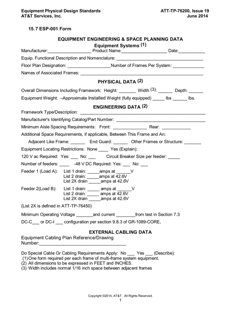
EQUIPMENT ENGINEERING & SPACE PLANNING DATA
Equipment Systems (1)
Manufacturer:__________________ Product Name:___________________ Date:___________
Equip. Functional Description and Nomenclature: ____________________________________
Floor Plan Designation: __________________Number of Frames Per System: _____________
Names of Associated Frames: ___________________________________________________
PHYSICAL DATA (2)
Overall Dimensions Including Framework: Height: _______ Width (3): ______ Depth: ______
Equipment Weight: –Approximate Installed Weight (fully equipped) _____ lbs ______ lbs.
ENGINEERING DATA (2)
Framework Type/Description: ____________________________________________________
Manufacturer's Identifying Catalog/Part Number: _____________________________________
Minimum Aisle Spacing Requirements: Front: ______________ Rear: ____________
Additional Space Requirements, if applicable, Between This Frame and An:
Adjacent Like Frame: ______
End Guard: ______ Other Frames or Structure: _______
Equipment Locating Restrictions: None ____ Yes (Explain):
120 V ac Required: Yes: ___ No: ___
Number of feeders: ____
Circuit Breaker Size per feeder: _____
-48 V DC Required: Yes: ___ No: ___
Feeder 1 (Load A):
List 1 drain: _____amps at ______V
List 2 drain: _____amps at 42.6V
List 2X drain _____amps at 42.6V
Feeder 2(Load B):
List 1 drain: _____ amps at ______V
List 2 drain: _____ amps at 42.6V
List 2X drain _____amps at 42.6V
(List 2X is defined in ATT-TP-76450)
Minimum Operating Voltage _______and current ________from test in Section 7.3
DC-C___ or DC-I ___ configuration per section 9.8.3 of GR-1089-CORE,
EXTERNAL CABLING DATA
Equipment Cabling Plan Reference/Drawing
Number:_________________________________
Do Special Cable Or Cabling Requirements Apply: No ___ Yes ___ (Describe):
(1) One form required per each frame of multi-frame system equipment.
(2) All dimensions to be expressed in FEET and INCHES.
(3) Width includes normal 1/16 inch space between adjacent frames
Copyright ©2014, AT&T . All Rights Reserved.
1
Equipment Physical Design Standards
AT&T Services, Inc.
ATT-TP-76200, Issue 19
June 2014
15.7 ESP-001
HEAT DISSIPATION DATA SHEET
Manufacturer: _________________________ Equipment: ____________________________ Date: _________________
List each active
Component in the system:
POWER
Description/Part/Card Number
List 1 Drain
(Watts)1
# of Units
HEAT DISSIPATION
(Count)
A: Max3
Possible
Per Unit (Watts)
B: AT&T4
Design
C: Max5
Possible
D: Nominal6
AT&T Design
HEAT DISSIPATION
TOTAL (Watts)
E: Maximum7
(A ) X (C) =
F: Nominal8
(B ) X (D) =
TOTAL WATTS FOR SYSTEM – REQUIRED FOR ALL
SUBMISSIONS
Airflow path design: –
REQUIRED FOR ALL SUBMISSIONS
Are equipment air flow path(s) only front (intake) to rear (exhaust) (FX – RX) ? Yes _____
No _______
If No:
•
•
Specify Path(s) ________________ _________________
________________
Attach a diagram depicting each of the path(s) & Specify direction of each of the flow(s)
Notes:
1)
2)
At no time shall Maximum Heat Dissipation be larger than List 1 Power Drain
Where possible, heat dissipation measurements should be measured rather than calculated.
• If the heat dissipation measurement is measured, follow the entry with a hyphen and the letter
“M” for measured
• If the heat dissipation measurement is calculated, follow the entry with a hyphen and the letter
“C” for calculated
• Examples: Measured = 4,000 – M or Calculated = 3,500 – C
• The “M” or “C” shall be included for each heat dissipation measurement entry
3)
A: Maximum possible is the total number of units that may be deployed in a system by
engineering design
Copyright ©2014, AT&T . All Rights Reserved.
2
Equipment Physical Design Standards
AT&T Services, Inc.
ATT-TP-76200, Issue 19
June 2014
4)
B: AT&T design is the total number of units that AT&T will typically deploys in a system.
• If the typical AT&T units deployed are unavailable, indicate the maximum number followed by a
hyphen and the letter “U” for unknown. (e.g. 4-U)
5)
C: Maximum possible is the maximum heat dissipation PER UNIT in Watts at full operating
parameters (i.e., 100% full load/traffic)
• This entry is NOT the worst case draw of the power supplies. Rather it is the full measured
calculated heat dissipation from a fully loaded, in operation part or system.
6)
D: Nominal is the heat dissipation PER UNIT in Watts while within normal operating
parameters (i.e., 50-74% full load/traffic)
• This entry is the Nominal (normal operating range) measured / calculated heat dissipation from a
typical AT&T loaded, in operation part or system.
7)
E: Maximum possible is the maximum heat dissipation TOTAL (# Units X Unit Heat) in Watts
at full operating parameters (i.e., 100% traffic)
• This entry is NOT the worst case draw of the power supplies. Rather it is the full measured /
calculated heat dissipation from a fully loaded, in operation part or system.
8)
F: Nominal is the heat dissipation TOTAL (# Units X Unit Heat) in Watts while within normal
operating parameters (i.e., 50-74% full load/traffic)
• This entry is the Nominal (normal operating range) measured / calculated heat from a typical
AT&T loaded, in operation part or system.
Copyright ©2013, AT&T . All Rights Reserved.
3
Equipment Physical Design Standards
AT&T Services, Inc.
ATT-TP-76200, Issue 19
June 2014
15. 8 ESP-002 Form
ENGINEERING & SPACE PLANNING EQUIPMENT DATA
Shelf Level Equipment Units (1)
Manufacturer:___________________ Product Name:_______________________ Date:___________
Unit Functional Description: __________________________________________________________
Product ID: ______________________
Nomenclature (Acronym): _________________________
Names of Associated Units per Function: _______________________________________________
EQUIPMENT DATA
Overall Dimensions (inches): Height:____ Depth (2) :_____ Width: _____
Unit Weight: Unit Installed Weight (fully equipped) _____ lbs
Minimum Aisle Spacing Requirements (feet & inches): Front: _________ Rear: __________
Requires 120 V ac: Yes ___ No ___Circuit Breaker Size per feeder: ____
Number of feeders: ___ -48 V DC: Yes: ___ No: ___
Feeder 1 (Load A):
List 1 drain: _____amps at ______V
List 2 drain: _____amps at 42.6V
List 2X drain _____amps at 42.6V
Feeder 2(Load B):
List 1 drain: _____ amps at ______V
List 2 drain: _____ amps at 42.6V
List 2X drain _____amps at 42.6V
(List 2X is defined in ATT-TP-76450)
Minimum Operating Voltage _______and current ________from test in Section 7.3
DC-C___ or DC-I ___ configuration per section 9.8.3 of GR-1089-CORE
Heat Baffles Required: Yes ___ No ___
If Yes, Supplied With Unit: Yes ___ No ___
UNIT TO FRAMEWORK MOUNTING DATA
Supported Mounting Flange Hole Patterns: 1 3/4 x 19" ___ 1 3/4 x 23" ___ 2 x 23" ___
Unit Mounts to Front of Framework Uprights: Yes ___ No ___
List Unit Locating Restrictions/Considerations if Any: ______________________________________
________________________________________________________________________________
Distance Unit Extends From Framework Mounting Surface: _____ (in.)
EXTERNAL CABLING DATA
Unit Cabling Plan Reference/Drawing Number: ___________________________________________
Unit Is Cabled From The Rear: Yes ___ No ___
Front and Rear: ______
Required Alarm Leads and Designations: _______________________________________________
Do Special Cable Or Cabling Requirements Apply: No ___ Yes ___ (Describe):
(1) One form required per each unit of a multi-unit product/system.
(2) Overall depth includes cable and its supporting apparatus.
Copyright ©2014, AT&T . All Rights Reserved.
4
Equipment Physical Design Standards
AT&T Services, Inc.
ATT-TP-76200, Issue 19
June 2014
15.8 ESP-002
HEAT DISSIPATION DATA SHEET
Manufacturer: _________________________ Equipment: ____________________________ Date:
_________________
List each active
Component in the system:
POWER
Description/Part/Card Number
List 1 Drain
(Watts)1
# of Units
(Count)
A: Max3
Possible
B: AT&T4
Design
HEAT DISSIPATION
Per Unit (Watts)
C: Max5
Possible
D: Nominal6
AT&T Design
HEAT DISSIPATION
TOTAL (Watts)
E: Maximum7
(A ) X (C) =
F: Nominal8
(B ) X (D) =
TOTAL WATTS FOR SYSTEM – REQUIRED FOR ALL
SUBMISSIONS
Airflow path design: –
REQUIRED FOR ALL SUBMISSIONS
Are equipment air flow path(s) only front (intake) to rear (exhaust) (FX – RX) ? Yes _____
No _______
If No:
•
•
Specify Path(s) ________________ _________________
________________
Attach a diagram depicting each of the path(s) & Specify direction of each of the flow(s)
Notes:
1) At no time shall Maximum Heat Dissipation be larger than List 1 Power Drain
2) Where possible, heat dissipation measurements should be measured rather than calculated.
• If the heat dissipation measurement is measured, follow the entry with a hyphen and the letter “M”
for measured
• If the heat dissipation measurement is calculated, follow the entry with a hyphen and the letter “C”
for calculated
• Examples: Measured = 4,000 – M or Calculated = 3,500 – C
• The “M” or “C” shall be included for each heat dissipation measurement entry
3) A: Maximum possible is the total number of units that may be deployed in a system by engineering
design
Copyright ©2013, AT&T . All Rights Reserved.
5
Equipment Physical Design Standards
AT&T Services, Inc.
ATT-TP-76200, Issue 19
June 2014
4) B: AT&T design is the total number of units that AT&T will typically deploys in a system.
5)
6)
7)
8)
• If the typical AT&T units deployed are unavailable, indicate the maximum number followed by a
hyphen and the letter “U” for unknown. (e.g. 4-U)
C: Maximum possible is the maximum heat dissipation PER UNIT in Watts at full operating
parameters (i.e., 100% full load/traffic)
• This entry is NOT the worst case draw of the power supplies. Rather it is the full measured
calculated heat dissipation from a fully loaded, in operation part or system.
D: Nominal is the heat dissipation PER UNIT in Watts while within normal operating parameters
(i.e., 50-74% full load/traffic)
• This entry is the Nominal (normal operating range) measured / calculated heat dissipation from a
typical AT&T loaded, in operation part or system.
E: Maximum possible is the maximum heat dissipation TOTAL (# Units X Unit Heat) in Watts at full
operating parameters (i.e., 100% traffic)
• This entry is NOT the worst case draw of the power supplies. Rather it is the full measured /
calculated heat dissipation from a fully loaded, in operation part or system.
F: Nominal is the heat dissipation TOTAL (# Units X Unit Heat) in Watts while within normal
operating parameters (i.e., 50-74% full load/traffic)
• This entry is the Nominal (normal operating range) measured / calculated heat from a typical AT&T
loaded, in operation part or system.
Copyright ©2013, AT&T . All Rights Reserved.
6

