DATA SHEET
CDC7630/7631 and DDC2353/2354 Series: Zero Bias Silicon
Schottky Barrier Detector Diodes
Applications
Microwave integrated circuits
Detectors
Features
High sensitivity
Low video impedance
Skyworks Green™ products are compliant with
all applicable legislation and are halogen-free.
For additional information, refer to Skyworks
Definition of Green™, document number
SQ04-0074.
Description
Applications
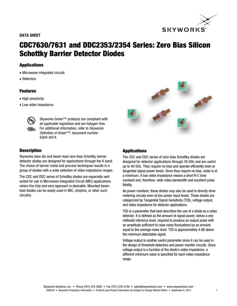
Skyworks bare die and beam-lead zero-bias Schottky barrier
detector diodes are designed for applications through the K band.
The choice of barrier metal and process techniques results in a
group of diodes with a wide selection of video impedance ranges.
The CDC and DDC series of zero-bias Schottky diodes are
designed for detector applications through 26 GHz and are useful
up to 40 GHz. They require no bias and operate efficiently even at
tangential signal power levels. Since they require no bias, noise is at
a minimum. A low video impedance means a short R-C time
constant and, therefore, wide video bandwidth and excellent pulse
fidelity.
The CDC and DDC series of Schottky diodes are especially well
suited for use in Microwave Integrated Circuit (MIC) applications
where the chip and wire approach is desirable. Mounted beamlead diodes can be easily used in MIC, stripline, or other such
circuitry.
As power monitors, these diodes may also be used to directly drive
metering circuits even at low power input levels. These diodes are
categorized by Tangential Signal Sensitivity (TSS), voltage output,
and video impedance for detector applications.
TSS is a parameter that best describes the use of a diode as a video
detector. It is defined as the amount of signal power, below a one
milliwatt reference level, required to produce an output pulse with
an amplitude sufficient to raise noise fluctuations by an amount
equal to the average noise level. TSS is approximately 4 dB above
the minimum detectable signal.
Voltage output is another useful parameter since it can be used in
the design of threshold detectors and power monitor circuits. Since
voltage output is a function of the diode’s video impedance, a
different minimum value is specified for each video impedance
range.
Skyworks Solutions, Inc. • Phone [781] 376-3000 • Fax [781] 376-3100 • sales@skyworksinc.com • www.skyworksinc.com
200843I • Skyworks Proprietary Information • Products and Product Information are Subject to Change Without Notice • September 8, 2014
1
SILICON SCHOTTKY BARRIER DIODES
Electrical and Mechanical Specifications
The absolute maximum ratings for the CDC and DDC series of
Schottky diodes are provided in Table 1. Electrical and physical
specifications are provided in Table 2. SPICE model parameters
for the CDC7630/7631 series are defined in Table 3.
Typical performance characteristics are shown in Figures 1
through 8. Typical video detector circuits are shown in Figure 9.
The multi-octave, high-sensitivity circuit would be used in Electronic
Countermeasures (ECM) and similar applications. An RF matching
structure that presents maximum power at the diode junction must
be incorporated to ensure maximum sensitivity.
The broadband low-sensitivity circuit would be used where a low
input VSWR is required. In this circuit, low VSWR is accomplished by
the use of the 50 Ω terminating resistor. Sensitivity, however, is
degraded by typically 10 dB from the multi-octave, high-sensitivity
circuit. The most common use for this circuit is in a broadband, flat
detector used primarily in the laboratory.
Package dimensions are provided in Figures 10 and 11. Additional
bonding and handling methods are contained in the Skyworks
Application Notes, Waffle Pack Chip Carrier Handling/Opening
Procedure (document #200146) and Diode Chips, Beam-Lead
Diodes, Capacitors: Bonding Methods and Packaging (document
#200532).
Table 1. CDC7630/7631 and DDC2353/2354 Diode Series Absolute Maximum Ratings (Note 1)
Maximum
Units
Reverse voltage
Parameter
VR
Symbol
Minimum
2
V
Forward current
IF
100
mA
RF input power @ TA = 25 °C
PD
75
mW
Storage temperature
TSTG
–60
+200
C
Operating temperature
TA
–55
+150
C
Electrostatic discharge:
ESD
<250
V
Human Body Model (HBM), Class 0
Note 1: Exposure to maximum rating conditions for extended periods may reduce device reliability. There is no damage to device with only one parameter set at the limit and all other
parameters set at or below their nominal value. Exceeding any of the limits listed here may result in permanent damage to the device.
CAUTION: Although this device is designed to be as robust as possible, electrostatic discharge (ESD) can damage this device. This device
must be protected at all times from ESD. Static charges may easily produce potentials of several kilovolts on the human body
or equipment, which can discharge without detection. Industry-standard ESD precautions should be used at all times.
Table 2. CDC7630/7631 and DDC2353/2354 Diode Series Electrical Specifications (Note 1)
(TA = +25 C, Characteristic Impedance [ZO] = 50 Ω, Unless Otherwise Noted)
Min. Detected Output
Voltage, EO
(mV)
Video Impedance, ZV
(Ω)
Max. TSS
(dBm)
Outline
Drawing
DDC2353-000
8
2000 to 6500
–52
491-006
DDC2354-000
15
5000 to 15000
–56
491-006
CDC7630-000
8
2000 to 6500
–52
571-006
CDC7631-000
15
5000 to 15000
–56
571-006
Part Number
Note 1: Performance is guaranteed only under the conditions listed in this table.
Skyworks Solutions, Inc. • Phone [781] 376-3000 • Fax [781] 376-3100 • sales@skyworksinc.com • www.skyworksinc.com
2
September 8, 2014 • Skyworks Proprietary Information • Products and Product Information are Subject to Change Without Notice • 200843I
DATA SHEET • CDC AND DDC SERIES: ZERO BIAS SCHOTTKY DIODES
Typical Performance Characteristics
+60
Tangential Signal Sensitivity (dBm)
Forward Current (mA)
10.0000
1.0000
Low Video Impedance Types
0.1000
0.0100
High Video Impedance Types
0.0010
0.0001
0
5
10
15
20
25
30
35
+58
+56
+54
Test Condition:
Video Bandwidth = 10 MHz
+52
+50
100
40
1000
10000
100000
Video Impedance (Ω)
Forward Voltage (mV)
Figure 1. Zero Bias Schottky Detector Diodes
Typical Forward DC Characteristics
Figure 2. Typical Zero Bias X-Band Detector Diodes
TSS vs Video Impedance
800
10000.00
100 kΩ
700
Output Voltage (mV)
Output Voltage (mV)
1000.00
100.00
ZV = 10 kΩ
10.00
Z V = 1 kΩ
1.00
ZV = 400 kΩ
0.10
0.01
–50
–40
–30
–20
Test Conditions:
f = 9.375 GHz
Load Resistance = 10 MΩ
–10
0
+10
+20
Input Power (dBm)
Figure 3. Typical Zero Bias X-Band Detector Diodes
Output Voltage vs Input Power as a Function of Video Impedance
50 kΩ
10 kΩ
600
500
400
1 kΩ
300
–40 –25 –10
+5 +20 +35 +50 +65 +80 +95
Temperature (°C)
Figure 4. Output Voltage vs Temperature
Over Load Resistance @ 0 dBm
Skyworks Solutions, Inc. • Phone [781] 376-3000 • Fax [781] 376-3100 • sales@skyworksinc.com • www.skyworksinc.com
200843I • Skyworks Proprietary Information • Products and Product Information are Subject to Change Without Notice • September 8, 2014
3
DATA SHEET • CDC AND DDC SERIES: ZERO BIAS SCHOTTKY DIODES
200
1000.00
180
+25 °C
Output Voltage (mV)
Output Voltage (mV)
100.00
–40 °C
10.00
+95 °C
1.00
100 kΩ
50 kΩ
160
10 kΩ
140
120
100
80
0.10
1 kΩ
60
40
–40 –25 –10
0.01
–30
–20
–10
0
+5 +20 +35 +50 +65 +80 +95
Temperature (°C)
Input Power (dBm)
Figure 5. Output Voltage vs Input Power Over Temperature
(Load Resistance = 1 kΩ)
Figure 6. Output Voltage vs Temperature Over Load Resistance
@ –10 dBm
1000
5
Output Voltage (mV)
Output Voltage (mV)
100 kΩ
4
+95 °C
100
+25 °C
–40 °C
10
50 kΩ
3
10 kΩ
2
1
1 kΩ
1
–30
0
–20
–10
0
Input Power (dBm)
Figure 7. Output Voltage vs Input Power Over Temperature
(Load Resistance = 100 kΩ)
–40 –25 –10
+5 +20 +35 +50 +65 +80 +95
Temperature (°C)
Figure 8. Output Voltage vs Temperature Over Load Resistance
@ –30 dBm
Skyworks Solutions, Inc. • Phone [781] 376-3000 • Fax [781] 376-3100 • sales@skyworksinc.com • www.skyworksinc.com
4
September 8, 2014 • Skyworks Proprietary Information • Products and Product Information are Subject to Change Without Notice • 200843I
DATA SHEET • CDC AND DDC SERIES: ZERO BIAS SCHOTTKY DIODES
Table 4. SPICE Model Parameters
Parameter
Part Number
Units
CDC7630-000
CDC7631-000
IS
A
5E-06
3.8E-06
RS
Ω
20
51
N
–
1.05
1.05
TT
sec
1E-11
1E-11
CJO
pF
0.14
0.08
M
–
0.4
0.4
EG
eV
0.69
0.69
XTI
–
2
2
FC
–
0.5
0.5
BV
V
2
2
IBV
A
1E-04
1E-04
VJ
V
0.34
0.34
RF Bypass
Input
Video Output
Load Resistor
DC Return
Multi-Octave: High-Sensitivity
RF Bypass
Input
Video Output
R = Z0
Load Resistor
Broadband: Low-Sensitivity
Figure 9. Typical Video Detector Circuits
Skyworks Solutions, Inc. • Phone [781] 376-3000 • Fax [781] 376-3100 • sales@skyworksinc.com • www.skyworksinc.com
200843I • Skyworks Proprietary Information • Products and Product Information are Subject to Change Without Notice • September 8, 2014
5
DATA SHEET • CDC AND DDC SERIES: ZERO BIAS SCHOTTKY DIODES
0.013 (0.33 mm)
0.011 (0.28 mm)
0.011 (0.28 mm)
0.009 (0.23 mm)
0.006 (0.15 mm)
0.004 (0.10 mm)
2 Plcs.
0.009 (0.23 mm)
0.007 (0.18 mm)
0.009 (0.23 mm)
0.007 (0.18 mm)
0.0006 (0.015 mm)
0.0003 (0.005 mm)
0.0025 (0.06 mm)
Max.
Top View
Schematic
Dimensions are in inches (millimeters shown in parentheses)
Figure 10. 491-006 Package Dimensions
Cathode/Bonding Pad
Diameter 0.0035 to 0.0045 (0.089 mm to 0.114 mm)
0.0095 (0.241 mm)
0.0115 (0.292 mm)
0.0095 (0.241 mm)
0.0115 (0.292 mm)
0.0085 (0.216 mm)
0.0065 (0.165 mm)
Backside Contact (Anode)
Gold Metallization
Dimensions are in inches (millimeters shown in parentheses)
S3181
Figure 11. 571-006 Package Dimensions
Skyworks Solutions, Inc. • Phone [781] 376-3000 • Fax [781] 376-3100 • sales@skyworksinc.com • www.skyworksinc.com
6
September 8, 2014 • Skyworks Proprietary Information • Products and Product Information are Subject to Change Without Notice • 200843I
DATA SHEET • CDC AND DDC SERIES: ZERO BIAS SCHOTTKY DIODES
Copyright © 2002-2012, 2014 Skyworks Solutions, Inc. All Rights Reserved.
Information in this document is provided in connection with Skyworks Solutions, Inc. (“Skyworks”) products or services. These materials, including the information contained herein, are provided by
Skyworks as a service to its customers and may be used for informational purposes only by the customer. Skyworks assumes no responsibility for errors or omissions in these materials or the
information contained herein. Skyworks may change its documentation, products, services, specifications or product descriptions at any time, without notice. Skyworks makes no commitment to
update the materials or information and shall have no responsibility whatsoever for conflicts, incompatibilities, or other difficulties arising from any future changes.
No license, whether express, implied, by estoppel or otherwise, is granted to any intellectual property rights by this document. Skyworks assumes no liability for any materials, products or
information provided hereunder, including the sale, distribution, reproduction or use of Skyworks products, information or materials, except as may be provided in Skyworks Terms and Conditions
of Sale.
THE MATERIALS, PRODUCTS AND INFORMATION ARE PROVIDED “AS IS” WITHOUT WARRANTY OF ANY KIND, WHETHER EXPRESS, IMPLIED, STATUTORY, OR OTHERWISE, INCLUDING FITNESS FOR A
PARTICULAR PURPOSE OR USE, MERCHANTABILITY, PERFORMANCE, QUALITY OR NON-INFRINGEMENT OF ANY INTELLECTUAL PROPERTY RIGHT; ALL SUCH WARRANTIES ARE HEREBY EXPRESSLY
DISCLAIMED. SKYWORKS DOES NOT WARRANT THE ACCURACY OR COMPLETENESS OF THE INFORMATION, TEXT, GRAPHICS OR OTHER ITEMS CONTAINED WITHIN THESE MATERIALS. SKYWORKS
SHALL NOT BE LIABLE FOR ANY DAMAGES, INCLUDING BUT NOT LIMITED TO ANY SPECIAL, INDIRECT, INCIDENTAL, STATUTORY, OR CONSEQUENTIAL DAMAGES, INCLUDING WITHOUT LIMITATION,
LOST REVENUES OR LOST PROFITS THAT MAY RESULT FROM THE USE OF THE MATERIALS OR INFORMATION, WHETHER OR NOT THE RECIPIENT OF MATERIALS HAS BEEN ADVISED OF THE
POSSIBILITY OF SUCH DAMAGE.
Skyworks products are not intended for use in medical, lifesaving or life-sustaining applications, or other equipment in which the failure of the Skyworks products could lead to personal injury,
death, physical or environmental damage. Skyworks customers using or selling Skyworks products for use in such applications do so at their own risk and agree to fully indemnify Skyworks for any
damages resulting from such improper use or sale.
Customers are responsible for their products and applications using Skyworks products, which may deviate from published specifications as a result of design defects, errors, or operation of
products outside of published parameters or design specifications. Customers should include design and operating safeguards to minimize these and other risks. Skyworks assumes no liability for
applications assistance, customer product design, or damage to any equipment resulting from the use of Skyworks products outside of stated published specifications or parameters.
Skyworks and the Skyworks symbol are trademarks or registered trademarks of Skyworks Solutions, Inc., in the United States and other countries. Third-party brands and names are for
identification purposes only, and are the property of their respective owners. Additional information, including relevant terms and conditions, posted at www.skyworksinc.com, are incorporated by
reference.
Skyworks Solutions, Inc. • Phone [781] 376-3000 • Fax [781] 376-3100 • sales@skyworksinc.com • www.skyworksinc.com
200843I • Skyworks Proprietary Information • Products and Product Information are Subject to Change Without Notice • September 8, 2014
7

