www.L-com.com
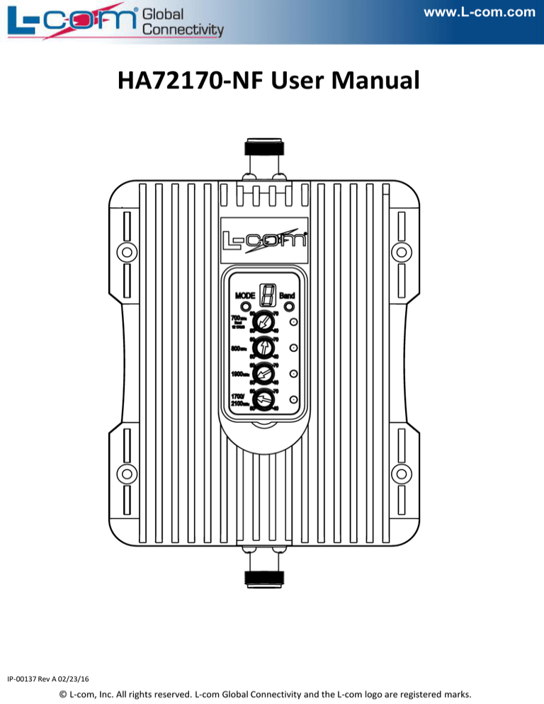
HA72170-NF User Manual
IP-00137 Rev A 02/23/16
© L-com, Inc. All rights reserved. L-com Global Connectivity and the L-com logo are registered marks.
www.L-com.com
HA72170-NF Installation
1.Operational overview
2. Step by step installation
Step 1: Mount the outside antenna (sold separately)
a. Choose right position
• Find the strongest signal position in the possible in
stall locations by read your cell phone signal bar;
• 30cm (1.0ft) away from any other metallic objects;
• 100cm (3.3ft) away from any windows;
Step 1: The powerful outside antenna captures voice and
data signal and transfers it to the booster;
Step 2: The booster receives the signal, amplifies it and
rebroadcasts it by inside mounted antenna.
Step 3: Your mobile devices get a better signal, never
experience dropped calls or slow data speed.
b.
Securely mount the outside antenna using hardware
supplied with antenna or one of the available
mounts available from L-com.
c.
•
•
Connect outside cable to the antenna
Make sure connectors are securely fastened
Seal the connectors with weatherproof tape
Supported Carriers
•
•
•
•
•
•
•
•
AT&T 2G/3G/4G (HSPA+ & LTE)
Verizon 3G/4G
T-Mobile 2G/3G/4G
Sprint 3G/4G
US Cellular 3G/4G
Metro PCS 3G/4G
Major Canadian Carriers 2G/3G/4G
All other carriers using 700MHz, 750MHz, 850MHz and
1900 MHz
Coverage Area
Note: The ability of coverage depends on output power of
booster. Any boost has a limit of amplification factor, so final
output power is related to received signal power level at the
outdoor mounted antenna.
Power level
at outdoor mounted antenna location
Coverage Area
(sq. ft.)
Strong
(5
bars on the cellphone)
12000
Medium
(3~4 bars on the cellphone)
8000
Weak
(1~2 bars on the cellphone)
800
IP-00137 Rev A 02/23/16
© L-com, Inc. All rights reserved. L-com Global Connectivity and the L-com logo are registered marks.
www.L-com.com
e.
•
•
Run the outside antenna cable into the building
Carefully arrange the cable along the building outside
making sure are no sharp bends;
Fix the cable at each corner;
Step 3: arrange the booster
a. Choose position
• Be sure to mount away from any heat source;
• In a ventilated dry place, temperature range should
-5° to +50° C (23° to 122° F);
b.
c.
Connect the outside antenna’s connector to the “outside”
labeled port of the booster;
Connect the inside antenna’s connector to the “inside”
labeled port of the booster;
Inside antenna
Outside antenna
Step 2: mount the inside antenna (sold separately)
a. Choose right position
• 20cm (0.6ft) away from any other metallic objects;
• 50cm (1.6ft) away from any windows;
• For the panel type antennas, position at the end of the
building is recommended;
Adapter cord
b.
Mount the inside antenna;
c.
Connect the inside cable to the inside antenna;
Step 4: power on the booster
a. Plug the power adapter to the AC power;
b. Attach the cord of the adapter to the booster;
Consumer Alert: BEFORE USE, you MUST REGISTER THIS DEVICE with your wireless provider and have your provider’s
consent. Most wireless providers consent to the use of signal boosters. Although AT&T, Sprint, T-Mobile, Verizon and 90
additional carriers have already given consent for all consumers to use this device, you must still register. Some providers
may not consent to the use of this device on their network. If you are unsure, contact your provider. You MUST operate
this device with approved antennas and cables as specified by the manufacturer. Antennas MUST be installed at least 20
cm (8 inches) from any person. You MUST cease operating this device immediately if requested by the FCC or a licensed
wireless service provider. WARNING. E911 location information may not be provided or may be inaccurate for calls served
by using this device.
IP-00137 Rev A 02/23/16
© L-com, Inc. All rights reserved. L-com Global Connectivity and the L-com logo are registered marks.
www.L-com.com
HA72170-NF LED Control Panel
The HA72170-NF LED control panel allows the user to set
the booster mode, select band and adjust the gain of
each frequency.
IP-00137 Rev A 02/23/16
© L-com, Inc. All rights reserved. L-com Global Connectivity and the L-com logo are registered marks.
www.L-com.com
HA72170-NF LED Control Panel
Band Indicator Lights
Steady Light: Normal
Flashing Light: Failure
IP-00137 Rev A 02/23/16
© L-com, Inc. All rights reserved. L-com Global Connectivity and the L-com logo are registered marks.
www.L-com.com
HA72170-NF LED Control Panel
LED Display
LED Display shows a number from
1 to 9, each number represents
difference booster output power
(downlink).
Number
Signal Intensity
Output Power (Downlink)
0
≤-80dBm
1
≥-60dBm
2
≥-55dBm
3
≥-50dBm
4
≥-45dBm
5
≥-30dBm
6
≥-15dBm
7
≥-5dBm
8
≥-0dBm
9
≥5dBm
E
Over Heat
F
Failure/Self Oscillation
IP-00137 Rev A 02/23/16
© L-com, Inc. All rights reserved. L-com Global Connectivity and the L-com logo are registered marks.
www.L-com.com
HA72170-NF LED Control Panel
Mode Button
By Pressing Mode Set Button, it switches the operation mode of the
control panel between 3 difference ways:
Manually
Select the
Band
MODE
Turn Off LED
display and all
Band
Indicator
Lights
Cyclic
Displaying
Manually
Select the
Band
IP-00137 Rev A 02/23/16
© L-com, Inc. All rights reserved. L-com Global Connectivity and the L-com logo are registered marks.
www.L-com.com
HA72170-NF LED Control Panel
Operational Modes
Cyclic
Displaying
When the operation mode of the control
panel has been set to Cyclic Displaying
Mode, the band indicator lights will flicker
from top to bottom in sequence, LED Display
shows the power level on each band.
Manually
Select the
Band
When the operation mode of the control
panel has been set to Manual Mode, by
pressing band select button you can choose
and lock the band to display its power level.
Band
IP-00137 Rev A 02/23/16
© L-com, Inc. All rights reserved. L-com Global Connectivity and the L-com logo are registered marks.
www.L-com.com
HA72170-NF LED Control Panel
LED Display
For best performance it is recommended to turn the Gain
Adjust Knobs so that the number 5, 6 or 7 is displayed on
the LED.
Examples
LED display shows signal intensity is 2 on
800MHz, the gain has been set to 40 dB, it is
the lowest level. Gently turning the blue knob
clockwise to increase the output power.
LED display shows signal intensity is 9 on
700MHz, the gain has been set to 70 dB, it is
the highest level. Gently turning the blue
knob anticlockwise to reduce the output
power to prevent potential self-oscillation.
IP-00137 Rev A 02/23/16
© L-com, Inc. All rights reserved. L-com Global Connectivity and the L-com logo are registered marks.
www.L-com.com
HA72170-NF LED Control Panel
LED Display
Examples
When LED Display shows “E”, turn OFF the
booster immediately, please check if there
is any heating source near the booster.
When LED Display shows “F”, it means selfoscillation has been occurred. It is possible
to fix by adjusting the knob or relocating
the antennas. Consulting with an
experienced technician is recommended.
IP-00137 Rev A 02/23/16
© L-com, Inc. All rights reserved. L-com Global Connectivity and the L-com logo are registered marks.
www.L-com.com
Finding The Strongest Signal Position
When installing the HA72170-NF’s outside antenna, aiming it towards the
best signal source from your service provider is important. The best way of
getting the strongest signal is to have one person rotate and aim the
outside antenna which should be connected to the booster.
While turning the outside antenna around 45 degrees at a time, a second
person is watching the signal strength on the phone inside the building.
This allows you to read the signal strength from the cell tower.
It is preferable to have the mobile phone is test mode:
iPhones – Dial *3001#12345#*
The top left corner will display signal strength.
Android Mobile Phones – The signal strength can be found in Settings –
About Phone – Mobile Networks – Signal Strength.
Also there are several apps available that allow you to measure exact signal
strength.
Signal readings usually appear as a negative number (for example, -68dBm).
The closer you get to zero the stronger the signal.
EXCELLENT
-50dB
-60dB
GOOD
-70dB
-80dB
POOR
-90dB
NO SIGNAL
-100dB
-110dB
IP-00137 Rev A 02/23/16
© L-com, Inc. All rights reserved. L-com Global Connectivity and the L-com logo are registered marks.
www.L-com.com
Warnings and Troubleshooting
WARNING:
Do Not Over Turn the Gain Adjust Knob to
blank area as shown. It may damage
booster and will invalidate warranty.
Warning: To prevent overheating, do not cover
Warning: To prevent damage to the booster,
the booster body with anything. Booster will shut
down when the temperature is too high.
proper lightning protection (available from L-com)
is recommended for all installations.
Warning: Use only the power supply provided by
Warning: Take extreme care to ensure that
L-com, any other products non-approved by L-com
or self-made power cable may damage the
booster.
Warning: Outdoor antenna must be orientated
to prevent the indoor antenna from receiving the
signal emitted by outside antenna. Otherwise this
will cause self-oscillation of the booster.
neither you nor the antenna comes near or in
contact with any electric power lines.
Troubleshooting
•
Proper Condition: The lights on the front panel
indicate the condition of the booster. Every
time the booster is powered on, all of the lights
will be lit in green for around 2 seconds and then
turn off, this means the booster pass the self
check and in good condition.
•
Wrong condition: If any of the lights are flashing
in green, than means the isolation between
the outside antenna and inside antenna is lower
than it should be and self oscillate occurred.
You must switch off the booster and check the
outside
antenna
and
inside
antenna
immediately. Make sure you have followed the
installation recommended and check every thing
carefully. If you can’t fix the problem please
contact technical support.
Warning: RF safety, any antenna used with this
device must be located 20 cm (8 inches) away
from persons or bystanders.
Warning: Both the mobile device and booster
will be damaged if connected directly by a cable.
Warning: Verify that both the outside and inside
antennas are connected to the booster before
powering up the booster.
Warning: Antenna installation is restricted to
height of 10 Meters (33 feet) or less above
ground, even if the antenna is installed indoors
when used with a mobile device that operates in
the 1710-1755 MHz band. Violation of this
requirement my subject the owner of the booster
to potential FCC enforcement actions.
IP-00137 Rev A 02/23/16
© L-com, Inc. All rights reserved. L-com Global Connectivity and the L-com logo are registered marks.
www.L-com.com
Network Protection Features
The HA72170-NF included safeguards to protect the cellular network
from interference. Each booster is individually tested and factory set
to ensure FCC compliance
1. The HA72170-NF cannot be adjusted with factory reprogramming
or disabling the hardware.
2. The HA72170-NF will amplify, but ONLY incoming and outgoing
signals in order to increase coverage of authorized frequency
bands.
3. If the HA72170-NF is not in use for five minutes, it will reduce
gain until a signal is detected.
4. If a detected signal is too high in a frequency band, or if the
booster detects an oscillation, the HA72170-NF will automatically
turn the power off on that band.
5. For a detected oscillation the booster will automatically resume
normal operation after a minimum of 1 minute. After 5 times
consecutive such automatic restarts, if the detected oscillation
still remains, any problematic bands are permanently shut off
unit the booster has been manually restarted by reconnecting
the power supply to the booster.
6. Noise power, gain and linearity are maintained by the boosters
microprocessor.
IP-00137 Rev A 02/23/16
© L-com, Inc. All rights reserved. L-com Global Connectivity and the L-com logo are registered marks.
www.L-com.com
Technical Specifications
Frequency
(MHz)
Gain
Uplink
Downlink
LTE
(band 12)
698-716
728-746
LTE
(band 13)
776-787
746-757
Cellular
( band5)
824-849
869-894
Output power
Uplink
55±2
55±2
55±2
Downlink
60±2
60±2
60±2
26±2dBm(Uplink)/0±2dBm(Downlink)
Noise figure
In-band Flatness
Weight
EIRP
Gain adjustment
Impedance
<5dB
<8dB
0.7Kg
1W
20dB
50 ohm
Operating temperature
-5°~60°
Current
≦1.5A(6V DC)
Dimension(mm)
155*125*25
PCS
(band 25/2)
1850-1910
1930-1990
AWS
(band 4)
1710-1755
2110-2155
60±2
65±2
60±2
65±2
IP-00137 Rev A 02/23/16
© L-com, Inc. All rights reserved. L-com Global Connectivity and the L-com logo are registered marks.


