ABELTRONICS
DIM11, DIM12, DIM13, DIM14
Rev. 7.0
10-01-2014
t: 01603 881076 e: sales@abeltronics.co.uk
www.abeltronics.co.uk
Unit 3 Frans Green Ind Est • Sandy Lane
East Tuddenham • Norfolk • NR20 3JG • UK
Low Voltage PWM Dimmer Modules, DIM11, DIM12, DIM13, DIM14
12V or 24V DC low voltage operation
Up to 10A load – 240W at 24V
No minimum load requirement
Lamp saving soft-start function
Works with LEDs, incandescent or halogen lamps
Flickerless dimming of LEDs (240Hz operation)
Drives the lamp on the high (positive) side
Voltage controlled, switch controlled or potentiometer controlled
16-bit resolution high-accuracy PWM, 256 dimming steps.
Fully protected and ruggedized
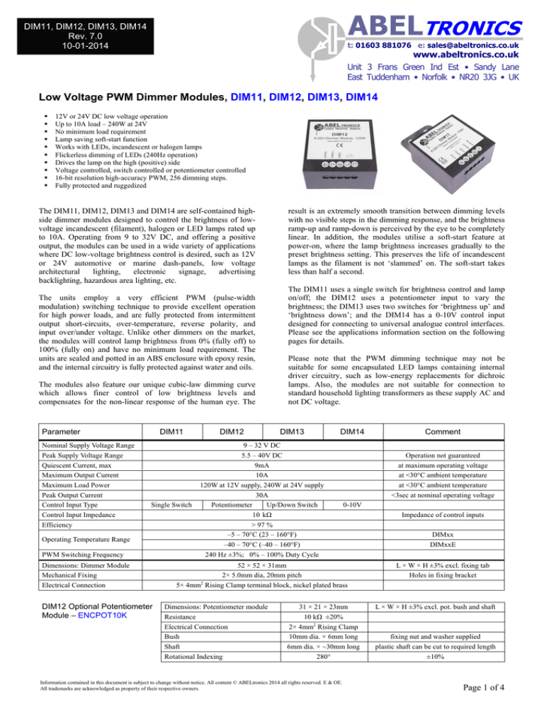
The DIM11, DIM12, DIM13 and DIM14 are self-contained highside dimmer modules designed to control the brightness of lowvoltage incandescent (filament), halogen or LED lamps rated up
to 10A. Operating from 9 to 32V DC, and offering a positive
output, the modules can be used in a wide variety of applications
where DC low-voltage brightness control is desired, such as 12V
or 24V automotive or marine dash-panels, low voltage
architectural
lighting,
electronic
signage,
advertising
backlighting, hazardous area lighting, etc.
The units employ a very efficient PWM (pulse-width
modulation) switching technique to provide excellent operation
for high power loads, and are fully protected from intermittent
output short-circuits, over-temperature, reverse polarity, and
input over/under voltage. Unlike other dimmers on the market,
the modules will control lamp brightness from 0% (fully off) to
100% (fully on) and have no minimum load requirement. The
units are sealed and potted in an ABS enclosure with epoxy resin,
and the internal circuitry is fully protected against water and oils.
The modules also feature our unique cubic-law dimming curve
which allows finer control of low brightness levels and
compensates for the non-linear response of the human eye. The
Parameter
Nominal Supply Voltage Range
Peak Supply Voltage Range
Quiescent Current, max
Maximum Output Current
Maximum Load Power
Peak Output Current
Control Input Type
Control Input Impedance
Efficiency
DIM11
Single Switch
Operating Temperature Range
PWM Switching Frequency
Dimensions: Dimmer Module
Mechanical Fixing
Electrical Connection
DIM12 Optional Potentiometer
Module – ENCPOT10K
DIM12
result is an extremely smooth transition between dimming levels
with no visible steps in the dimming response, and the brightness
ramp-up and ramp-down is perceived by the eye to be completely
linear. In addition, the modules utilise a soft-start feature at
power-on, where the lamp brightness increases gradually to the
preset brightness setting. This preserves the life of incandescent
lamps as the filament is not ‘slammed’ on. The soft-start takes
less than half a second.
The DIM11 uses a single switch for brightness control and lamp
on/off; the DIM12 uses a potentiometer input to vary the
brightness; the DIM13 uses two switches for ‘brightness up’ and
‘brightness down’; and the DIM14 has a 0-10V control input
designed for connecting to universal analogue control interfaces.
Please see the applications information section on the following
pages for details.
Please note that the PWM dimming technique may not be
suitable for some encapsulated LED lamps containing internal
driver circuitry, such as low-energy replacements for dichroic
lamps. Also, the modules are not suitable for connection to
standard household lighting transformers as these supply AC and
not DC voltage.
DIM13
DIM14
9 – 32 V DC
5.5 – 40V DC
9mA
10A
120W at 12V supply, 240W at 24V supply
30A
Potentiometer
Up/Down Switch
10 kΩ
> 97 %
–5 – 70°C (23 – 160°F)
–40 – 70°C (–40 – 160°F)
240 Hz ±3%; 0% – 100% Duty Cycle
Operation not guaranteed
at maximum operating voltage
at <30°C ambient temperature
at <30°C ambient temperature
<3sec at nominal operating voltage
0-10V
52 × 52 × 31mm
2× 5.0mm dia, 20mm pitch
5× 4mm2 Rising Clamp terminal block, nickel plated brass
Dimensions: Potentiometer module
Resistance
Electrical Connection
Bush
Shaft
Rotational Indexing
31 × 21 × 23mm
10 kΩ ±20%
2× 4mm2 Rising Clamp
10mm dia. × 6mm long
6mm dia. × ~30mm long
280°
Information contained in this document is subject to change without notice. All content © ABELtronics 2014 all rights reserved. E & OE.
All trademarks are acknowledged as property of their respective owners.
Comment
Impedance of control inputs
DIMxx
DIMxxE
L × W × H ±3% excl. fixing tab
Holes in fixing bracket
L × W × H ±3% excl. pot. bush and shaft
fixing nut and washer supplied
plastic shaft can be cut to required length
±10%
Page 1 of 4
ABELTRONICS
DIM11, DIM12, DIM13, DIM14
Rev. 7.0
10-01-2014
t: 01603 881076 e: sales@abeltronics.co.uk
www.abeltronics.co.uk
Unit 3 Frans Green Ind Est • Sandy Lane
East Tuddenham • Norfolk • NR20 3JG • UK
Mounting and Connection Guidelines
The power supply to the dimmers typically comes from a suitably
rated low-voltage DC supply in the range 9 – 32V which must be
fused at 10A or less to protect the modules. If using a switchedmode power supply with the modules, we recommend the supply
be rated at 1.5 times the expected maximum lamp current.
The dimmers use the PWM dimming technique and do not
change the system voltage. The power supply voltage, therefore,
must be matched to the load. If using 12V LEDs or lamps, use a
12V power supply. If using 24V LEDs or lamps, use a 24V
power supply.
The dimmers will run warm when operating loads exceeding 5A,
therefore it is important to securely bolt the metal fixing tab to a
suitable metal surface to allow heat to be dissipated. The fixing
bracket has two 5mm diameter holes drilled 20mm apart and is
manufactured from zinc plated steel. The units should be
mounted in a cool location, away from sources of heat.
Connection terminals are high quality rising-clamp terminal
blocks capable of receiving up to 4mm2 cable. The terminals are
spaced 5mm pitch. To maximise the potential of the DIM
modules, cable rated at currents exceeding the lamp load by 1.5
times should be used to connect the modules, and the use of a
bootlace ferrule at the DIMxx terminals is recommended. The
dimmers are capable of controlling high currents and it is
important to ensure the screw terminals are very tight to prevent
them overheating.
The modules are sealed in epoxy resin in an ABS enclosure and
are fully resistant to moisture and oils. The screw terminals are
exposed however, and despite being nickel plated, could be
susceptible to corrosion in extreme environments. It is
recommended that exposure to acids and salts is minimised. For
extreme applications corrosion-proof IP68-rated wire-ended
modules are available, please contact ABELtronics for more
information.
Temperature Ranges
The DIMxx series operate from –5 to +70 Celsius. Extended
temperature range modules are available operating from –40 to
+70 Celsius – add the suffix ‘E’ to the part number. For example
DIM14E is an extended temperature range DIM14 unit.
DIM11 Applications Information
A single momentary switch completely controls the dimmer operation: a brief press of the switch will toggle the lamp on or off, and a
sustained press will cause the lamp brightness to ramp up or down for as long as the switch is held, repeating until the switch is released at
the desired brightness level.
The Mode input controls the operating behaviour of the unit and should be connected during installation. Leaving the Mode terminal
unconnected, when the lamp is turned on by a brief press of the control switch it will always initially operate at full brightness. The
brightness level can then be changed by a sustained press of the control switch. The lamp will revert to full brightness when the lamp is
turned off and back on again.
With the Mode input connected to the +Supply terminal, when the
lamp is turned on, the previously stored brightness level is retrieved.
The level can then be adjusted with a sustained press of the control
switch. When the lamp is turned off, or when power to the module is
lost, the current brightness setting is stored for retrieval next time.
Mode Input Connected to…
DIM11
Unconnected:
Always full brightness at
power-on
Control Pushbutton
Switch
+ Output
+ Supply
Ground
Mode (see text)
10A Fuse
+
Supply
–
Lamps, LEDs, etc
10A Max total load
+Supply:
Recall last saved brightness at
power-on
Regardless of the Mode input, the last-saved brightness level and
on/off state are recalled when power to the unit is first applied. This
ensures the current brightness level is not lost when power is removed,
and any power glitches to the unit will not cause the lamp to suddenly
change brightness or on/off state once stable power is restored.
In addition, the brightness ramp direction swaps between switch
presses. In other words, if the brightness is currently increasing, the
next sustained press of the control switch will cause the brightness to
decrease, and vice-versa. This allows the user to adjust the brightness
accurately and quickly.
The Control pushbutton can be any momentary pushbutton switch, or
relay contact. The DIM11 is supplied without a switch; a selection of
pushbuttons is available separately from ABELtronics.
Information contained in this document is subject to change without notice. All content © ABELtronics 2014 all rights reserved. E & OE.
All trademarks are acknowledged as property of their respective owners.
Page 2 of 4
ABELTRONICS
DIM11, DIM12, DIM13, DIM14
Rev. 7.0
10-01-2014
t: 01603 881076 e: sales@abeltronics.co.uk
www.abeltronics.co.uk
Unit 3 Frans Green Ind Est • Sandy Lane
East Tuddenham • Norfolk • NR20 3JG • UK
DIM12 Applications Information
Supplied Potentiometer
The DIM12 is controlled by means of the supplied rotary
potentiometer. The potentiometer is mounted remotely
from the DIM12 and is connected using 2-core cable. The
terminals of the potentiometer should be soldered to one
end of the 2-core cable; the other end of the cable is
connected to the DIM12 as shown. Turning the
potentiometer shaft clockwise will increase the lamp
brightness, anti-clockwise will decrease the lamp
brightness. The DIM12 features a fail-safe feature whereby
in the event of an open circuit between the DIM12 and the
potentiometer module, the output will default to full
brightness.
DIM12
No Connection
Potentiometer
+ Output
+ Supply
Ground
Potentiometer
The DIM12 can be used with any 10kΩ linear
potentiometer, other than the supplied potentiometer. Only
two terminals of the potentiometer need to be connected to
the DIM12: the wiper (central) terminal and left-most
terminal with the shaft facing you. An optional fully
enclosed potentiometer module is available separately
featuring screw terminals for easier connection. Please see
www.abeltronics.co.uk/products/encpot10k.
10A Fuse
+
Lamps, LEDs, etc
10A Max total load
Supply
–
DIM13 Applications Information
The DIM13 is controlled by a two position centre-off rocker switch or two pushbuttons. Connections to the DIM13 are shown below. The
‘Increase’ and ‘Decrease’ inputs should be switched to +Supply through a suitable momentary rocker switch or pushbuttons (not supplied) –
a centre-off momentary rocker switch is shown below-right, and pushbuttons are shown below-left. When the rocker or pushbutton is pressed
in the ‘Brighter’ direction, the lamps will get brighter, conversely for the ‘Dimmer’ direction. A brief press of the switch will increase or
decrease the brightness a small amount. If the switch is pressed continuously, the brightness will increase or decrease for as long as the
switch is held, until either the fully-on or fully-off state is reached. Pressing both switches simultaneously has no effect on the brightness.
The ‘switch’ can be any kind of switch, including relay contacts.
The DIM13 also has a built-in function where the current brightness setting is saved into non-volatile memory every time it is changed. The
brightness level remains in memory even when power is removed, and is restored when power is re-applied. This ensures the preset
brightness level is not lost when power is removed.
DIM13 connection diagram –
using a centre off (on)-off-(on) rocker switch
DIM13 connection
diagram – using
pushbuttons
Push: Dimmer
DIM13
DIM13
Centre-off momentary
Rocker Switch
Push: Brighter
Push: Dimmer
Decrease
–
Increase
10A Fuse
10A Fuse
+
+
Supply
+ Output
Push: Brighter
+ Supply
Ground
+ Output
+ Supply
Ground
Decrease
Increase
Lamps, LEDs, etc
10A Max total load
Supply
Lamps, LEDs, etc
10A Max total load
–
Information contained in this document is subject to change without notice. All content © ABELtronics 2014 all rights reserved. E & OE.
All trademarks are acknowledged as property of their respective owners.
Page 3 of 4
ABELTRONICS
DIM11, DIM12, DIM13, DIM14
Rev. 7.0
10-01-2014
t: 01603 881076 e: sales@abeltronics.co.uk
www.abeltronics.co.uk
Unit 3 Frans Green Ind Est • Sandy Lane
East Tuddenham • Norfolk • NR20 3JG • UK
DIM14 Applications Information
PLC, Crestron™ or
universal controller
(current sourcing)
The DIM14 is controlled by a universal 0-10V
analogue voltage input. The control input is
designed to accept an analogue 0-10V control signal
from a PLC, lighting controller, Crestron™ or
Lutron™ controller, or similar, as long as the
controller is a current-sourcing type. As the input
signal is varied between 0 and 10V the connected
lamp changes in brightness. An input of less than
0.2V turns the lamp fully off, and more than 9.8V
turns the lamp fully on.
DIM14
0-10V Out
Ground
The 0-10V input is protected against over-voltage,
although it should never exceed the module’s supply
voltage. The control voltage input and the DIM14
supply voltage are not electrically isolated from each
other and share a common ground. The two ground
terminals on the module are internally connected
together.
0-10V
+ Output
+ Supply
Ground
The ‘Ground’ terminals are
connected together inside the
DIM14
Ground
10A Fuse
+
Lamps, LEDs, etc
10A Max total load
Supply
Please see the DIM14 application note available at
www.abeltronics.co.uk/products/dim14 for further
information on how to reduce the likelihood of
ground-loop noise affecting the dimmer’s
performance.
–
The 0-10V input is a current-sinking type which means it muse be connected to a current-sourcing controller. (The controller must provide
the 0-10V signal; the DIM14 does not output any voltage back down the 0-10V line). ABELtronics does manufacture current-sourcing
versions of the DIM14, but due to the wide variety of current-sinking controllers on the market we produce the units on an ad-hoc basis.
Please contact us for further information.
Dimensional Drawing
Further Information
40.0
For more information, links to other products and
to download the most current datasheet, please
visit www.abeltronics.co.uk/dimmers. If you have
any questions or queries, or require one of our
dimmers to be modified to fit your application,
please
contact
us
by
visiting
www.abeltronics.co.uk
32.5
1.6
7.6
28.0
20.0
90° ±5°
Also Available
Ø 5.2
DIM15 – Radio Controlled remote dimmer
DIM10 – Power booster for DIMxx Modules to
allow an unlimited load to be controlled
DIMxx
DIM13-2DIN – Dual Output DIM13, DIN-Mount
Wire Inlet
8mm deep x 3mm dia.
51.5
5
5
5
5
9.7
Multichannel dimmers in various configurations
are available.
Please visit www.abeltronics.co.uk/dimmers for
more information.
6.0
51.5
30.3
All dimensions in mm
Information contained in this document is subject to change without notice. All content © ABELtronics 2014 all rights reserved. E & OE.
All trademarks are acknowledged as property of their respective owners.
Page 4 of 4


