tray return conveyor
advertisement

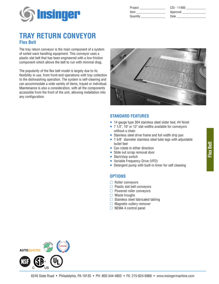
Project ________________ Item __________________ Quantity _______________ CSI - 11400 _____________ Approval _______________ Date ___________________ TRAY RETURN CONVEYOR Flex Belt The tray return conveyor is the main component of a system of soiled ware handling equipment. This conveyor uses a plastic slat belt that has been engineered with a low-friction component which allows the belt to run with minimal drag. The popularity of the flex belt model is largely due to its flexibility in use, from front-end operations with tray collection to the dishwashing operation. The system is self-cleaning and can accommodate a wide variety of items, trayed or individual. Maintenance is also a consideration, with all the components accessible from the front of the unit, allowing installation into any configuration. 14 gauge type 304 stainless steel slider bed, #4 finish 7 1/2", 10" or 12" slat widths available for conveyors without a chain Stainless steel drive frame and full width drip pan 1 5/8" diameter stainless steel tube legs with adjustable bullet feet Can rotate in either direction Slide out scrap removal door Start/stop switch Variable Frequency Drive (VFD) Detergent pump with built-in timer for self cleaning OPTIONS Roller conveyors Plastic slat belt conveyors Powered roller conveyors Waste troughs Stainless steel fabricated tabling Magnetic cutlery remover NEMA 4 control panel 6245 State Road • Philadelphia, PA 19135 • PH: 800-344-4802 • FX: 215-624-6966 • www.insingermachine.com Flex Belt STANDARD FEATURES TRAY RETURN CONVEYOR Flex Belt SPECIFICATIONS BELTING- The slats are designed with tapered wings and hold-down tabs on the bottom to contain the belt and prevent it from jumping the track in the corners. The tabs also support the belt on the return track monorail. CONVEYOR SLIDERBED- The belt is supported by and runs on high-density polyethylene wear strips that are connected to the centerline support grove which is integrated to the standard 14 gauge 304 stainless steel #4 finish conveyor slider bed. RETURN TRACK- A monorail type return track, supported from the bottom side of the conveyor slider bed, is provided. The return track consists of an upside-down “C” channel made of high-density polyethylene which supports the belt by suspending it by its tabs. A full width stainless steel pan is provided, approximately 1/8” below the belt to carry water from the belt wash to the tail unit. 10-year warranty on the return track. DRIVE FRAME- Consisting of all-welded stainless steel angle frame with integral 15/8” diameter stainless steel tube legs and adjustable stainless steel bullet feet. WASH TANK- Wash tank to be all-welded 14 gauge stainless steel with hinged-down access door designed to be watertight and supplied with cabinet latch. A perforated stainless steel lift-out scrap basket, accessible through the access door, is provided. The sprockets for transfer of power from the motor/gearbox to the belt, drive shaft, and bearings is supported by the wash tank. The drive chain used to transfer power from the sprocket on the gearbox to the sprocket on the drive shaft is s/s #50 and is located on the front side of the drive unit behind the hinged access door. ENCLOSURE FOR DRIVE UNIT- The conveyor is supplied with an enclosure for the drive unit. The enclosure is fitted with 20 gauge stainless steel end panels and both doors on the front are hinged 16 gauge stainless steel. The door that gives access to the chain and sprockets acts as a chain guard and are screwed shut. DRIVE SHAFT- A 1” diameter stainless steel drive shaft is provided and mounted within the wash tank on double-sealed bearings inside the tank and standard precision ball bearing flanged cartridge outside the tank. BELT WASH- Spray jets connected to manifolds are located strategically inside the wash tank to clean the belt are provided. Manifolds areasily removable without tools. PLUMBING COMPONENTS- Plumbing components are ½” brass, copper or pvc fittings and include hot and cold water shut-off/ mixing valve, line strainer, check valve and solenoid valve to ensure that water is on when conveyor is running, all located inside the drive unit. Liquid proportioning injector with flow adjustment to supply detergent from a remote container and inject it directly into the water line before entering the spray manifolds is included. DRIVE MOTOR- Totally enclosed fan cooled (TEFC) stainless steel drive motor. MAIN CONTROL PANEL- A main control panel containing start/stop switches, belt wash, belt speed control, plate rinse, indicating lights, sealed disconnect and control transformer (24 volt secondary) sized to suit the system comes standard. All components are neatly contained in a stainless steel waterproof enclosure. Auxiliary start/stops and accumulation efficient switches may be provided as required to ensure efficient operation of the system. An electrical contractor will bring 15 amp/208 Volt/ 3-phase power to the main of the panel. Wiring from the equipment panel and all wiring is carried in liquid tight conduits, including conveyor motor and controls. All electrical controls are approved for wet conditions and comply with all electrical codes. All enclosures for electrical components are watertight. TAIL UNIT- A 14 gauge stainless steel tank with hinge-down access door, latch and perforated stainless steel scrap basket similar to the one in drive unit. The tail tank contains tail shaft and tail belt sprocket assembly mounted directly to side of the tank by stainless steel bolts. CONNECTIONS Plumbing – At drive unit – 1½” waste; ½” hot and cold water Plumbing – At tail unit – 1½” waste Electrical – According to location on drawing 15 amp/ 208 volt/ 3-phase/ 60 cycle APPROVALS- The tray return conveyor is manufactured to conform to the highest applicable CSA and NSF standards. Note: Due to product improvement we reserve the right to change information and specifications without notice. 6245 State Road • Philadelphia, PA 19135 • PH: 800-344-4802 • FX: 215-624-6966 • www.insingermachine.com 3_2012

