®
Fluke DP120, Pomona 6731
Differential Voltage Probe
Service Sheet
4822 872 05374
Service Centers
For service information, contact your local Fluke service center. To locate an authorized service center, visit us
on the World Wide Web:
http://www.fluke.com
or call Fluke using any of the phone numbers listed below:
+1-888-993-5853 in U.S.A. and Canada
+31-40-2675200 in Europe
+1-425-446-5500 from other countries
General Safety Information
Disconnect the differential voltage probe from all voltage sources before you open the covers.
Warning
Servicing described in this service sheet is to be done by qualified service personnel. To avoid
electrical shock, do not service the differential voltage probe unless you are qualified to do so.
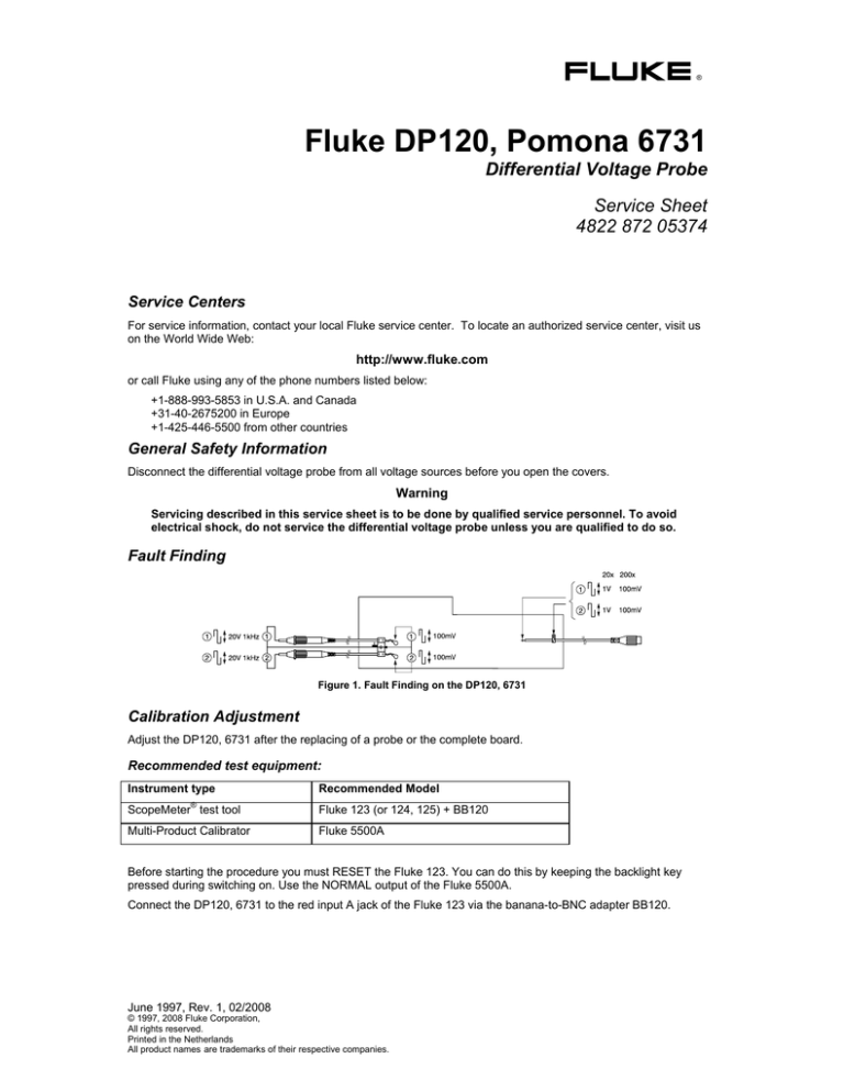
Fault Finding
Figure 1. Fault Finding on the DP120, 6731
Calibration Adjustment
Adjust the DP120, 6731 after the replacing of a probe or the complete board.
Recommended test equipment:
Instrument type
®
Recommended Model
ScopeMeter test tool
Fluke 123 (or 124, 125) + BB120
Multi-Product Calibrator
Fluke 5500A
Before starting the procedure you must RESET the Fluke 123. You can do this by keeping the backlight key
pressed during switching on. Use the NORMAL output of the Fluke 5500A.
Connect the DP120, 6731 to the red input A jack of the Fluke 123 via the banana-to-BNC adapter BB120.
June 1997, Rev. 1, 02/2008
© 1997, 2008 Fluke Corporation,
All rights reserved.
Printed in the Netherlands
All product names are trademarks of their respective companies.
Figure 2. Adjusting elements
Step
Input Signal/Connections
DP120
Setting Fluke 123
Adjust
Reading Fluke 123
c
Short circuit red and black probe (use
AC85A)
20 x
50 mV/div.
10 ms/div.
R29
Adjust to zero
d
Apply: Sine wave, 20Vpp, 60Hz
20 x
R19
LF-CMRR
Connect:
Red and black probe to HI Fluke 5500
LO Fluke 5500 to COM Fluke 123
10 mV/div.
10 ms/div.
Adjust to minimum
signal
e
Apply: Square wave, 20Vpp, 1 kHz
20x
Connect:
Red probe to HI Fluke 5500
Black probe to LO Fluke 5500
200 mV/div.
100 μs/div.
C16
LF square wave
response
Adjust for a flat
pulse top
f
Apply: Sine wave, 20 Vpp, 100 kHz
20x
Connect:
Red and black probe to HI Fluke 5500
LO Fluke 5500 to COM Fluke 123
10 mV/div.
10 μs/div.
C26
MF-CMRR
Adjust to minimum
signal
g
Short circuit red and black probe (use
AC85A)
20x
10 mV/div.
10 ms/div.
R29
Adjust to zero
Offset (coarse)
Offset (fine)
WAVEFORM:
SMOOTH
h
Apply: + 100 Vdc
Gain 20x
Connect:
Red probe to HI Fluke 5500
Black probe to LO Fluke 5500
i
Apply: + 1000 Vdc
Gain 200x
Connect:
Red probe to HI Fluke 5500
Black probe to LO Fluke 5500
20x
AUTO
R38
Adjust meter reading
to:
5V ± 0.125V
200x
AUTO
R33
Adjust meter reading
to:
5V ± 0.125V
Repairing the Probe
Warning
To avoid electrical shock, disconnect power supply and probes from any live source and from
the differential voltage probe itself. Always remove the battery before completely disassembling
the probe. If repair of the disassembled probe is required, it shall be carried out only by qualified
personnel using customary precautions against electric shock.
Figure 3. Exploded View
Replaceable Parts
Contact your local Fluke representative. To ensure prompt delivery of the correct part, include the following
information when you place an order:
- Instrument model (DP120 or 6731)
- Ordering code
- Item number
- Description
- Quantity
Refer to the exploded view (Figure 3) for the item numbers.
Item
Ordering Code
Description
1
199265
BNC Cable, 50 cm
2
188539
Cable Grommet
3
190188
Cable Clamp
4
3304974
Battery Connection Cable
5
142288
9V Alkaline Battery
6
188562
Bottom Cover
7
188573
Captive Screw M3x20
8a
199288
Top Text Plate Fluke DP120
8b
3304963
Top Text Plate Pomona 6731
9
188557
Top Cover
10
188547
Slider
11
199262
Printed Circuit Assembly
12
190063
Cable Clamp
13
199281
Front Cover
14a
199296
Front Text Plate Fluke DP120
14b
3304956
Front Text Plate Pomona 6731
15
199254
Red Probe Assembly, 1.5m
16
199257
Black Probe Assembly, 1.5m
17
AC283
Pin-Grabber Test Clips (Red&Black)
18
AC285
Large Jaw Alligator Clips (Red&Black)
19
199304
Warning Sticker
20
199299
Metal Screening
21
199270
Crimp Bus
22
199273
Corner Grommet
23
187455
Clip
Optional Accessories
Available power adapters:
Model
Description
PM8907/801
Universal Europe 230V, 50 Hz
PM8907/803
North America 120V, 60 Hz
PM8907/804
United Kingdom 240V, 50 Hz
PM8907/806
Japan 100V, 60 Hz
PM8907/807
Australia 240V, 50 Hz
PM8907/808
Universal 115V/230V
Note
The 230V rating of the PM8907/808 is not for use in North America. A line plug adapter complying with the applicable
National Requirements may be provided to alter the blade configurations for a specific country.


