ISSN 2348 – 9928
IJAICT Volume 1, Issue 10, February 2015
Doi:01.0401/ijaict.2015.10.06 Published on 05 (03) 2015
DIMINISHING THE REQUIREMENT OF POWER USING PLC AND
SCADA SYSTEMS IN POWER GRID SYSTEM
Mr. T. Vignesh
Assistant Professor,
Department of EEE,
Jay Shriram Group of Institutions,
Tirupur, Tamilnadu, India
Abstract— Power management is an important constraint in the design of various loads in industries for automation. So if power consumption increases then the substation monitoring is very important for the purpose of controlling the hardware and software optimization with the help of PLC ladder logic system and SCADA were used. This technique in order to reach strong conclusion about their actual impact on the power grid monitoring and control without manpower. The basic idea behind substation control project is to monitor the switchyards in substation. In substation many relays and circuit breakers are used. When any one breaker is trip because of the problems, we can monitor and control through SCADA windows. In power management project, the computer is used for assigning the priority for various loads. The signals are given to the computer of the electricity board where there is the electronic control unit which controls the sequence of disconnecting the load. On basis of controls from the computer the breakers are managed and in computer the
SCADA system is installed which is used for monitoring and control. If there any problem occurs in plant, we can easily identify which part is trip.Afterthat we can troubleshoot the problem through manpower and monitor the substation.
Keywords — PLC, SCADA, Power Grid System, Fault Isolation.
I.
INTRODUCTION
1.1
SCADA
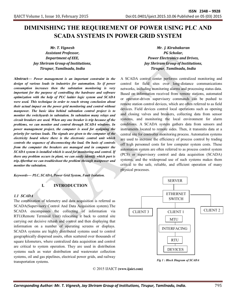
The combination of telemetry and data acquisition is referred as
SCADA(Supervisory Control And Data Acquisition system).The
SCADA encompasses the collecting of information via
RTU(Remote Terminal Unit) relocating it back to central site carrying out decisive rehash and control and then displaying that information on a number of operating screens or displays.
SCADA systems are highly distributed systems used to control geographically dispersed assets, often scattered over thousands of square kilometers, where centralized data acquisition and control are critical to system operation. They are used in distribution systems such as water distribution and wastewater collection systems, oil and gas pipelines, electrical power grids, and railway transportation systems.
Mr. J. Kirubakaran
PG Scholar,
Power Electronics and Drives,
Jay Shriram Group of Institutions,
Tirupur, Tamilnadu, India
A SCADA control center performs centralized monitoring and control for field sites over long-distance communications networks, including monitoring alarms and processing status data.
Based on information received from remote stations, automated or operator-driven supervisory commands can be pushed to remote station control devices, which are often referred to as field devices. Field devices control local operations such as opening and closing valves and breakers, collecting data from sensor systems, and monitoring the local environment for alarm conditions. A SCADA system gathers data from sensors and instruments located to remote sides. Then, it transmits data at a central site for controller monitoring process. Automation systems are used to increase the efficiency of process control by trading off high personnel costs for low computer system costs. These automation system are often referred to as process control system
(PCS) or supervisory control and data acquisition (SCADA) systems, and the widespread use of such systems makes them critical to the safe, reliable, and efficient operation of many physical processes.
SERVER
ETHERNET
SWITCH
CLIENT 1
CLIENT 2
CLIENT 3
MTU
INTERFACING
RTU
DEVICES
Fig 1 : Block Diagram of SCADA
© 2015 IJAICT (www.ijaict.com)
Corresponding Author: Mr. T. Vignesh, Jay Shriram Group of Institutions, Tirupur, Tamilnadu, India.
795
ISSN 2348 – 9928
IJAICT Volume 1, Issue 10, February 2015
Doi:01.0401/ijaict.2015.10.06 Published on 05 (03) 2015
The broad architecture of a SCADA involves physical equipment such as switches, pumps, and other devices able to be controlled by a Remote Telemetry Unit (RTU). The dual roles of the master computers are to provide the information such as meter readings and equipment status to human operators in a digestible form and to allow the operators to control the field equipment the master computers, and interface with the system using operator consoles which communicate with the master computers over a network.
Master Terminal Unit (MTU) – allows operators to view the state of any part of the plant equipment and drives most operator interaction with the by alarms. It provides displays of process status information, including alarms and other means.
Interfacing – allows communications equipment from different manufacturers to be connected together. The RS 232 or RS-485 interface is designed for the connection of two devices. Two devices called: DTE (Data Terminal Equipment) communicates with a DCE device and transmits data and receives data and DCE
(Data communications Equipment) transmits data between the operation are typically stored in battery-backed-up or non-volatile memory . The functionality of the PLC has evolved over the years to include sequential relay control, motion control, process control, distributed control systems and networking. The data handling, storage, processing power and communication capabilities of some modern PLCs are approximately equivalent to desktop computers.
The main difference from other computers is that PLCs are armored for severe conditions (such as dust, moisture, heat, cold) and have the facility for extensive input/output (I/O) arrangements.
DTE and a physical data communications link.
Remote Terminal Unit (RTU) – means a microprocessor to connect data input streams to data output streams. RTU may
Fig 2 : Basic Block Diagram of PLC include a battery or charger circuitry. It is accomplished by using an isolated voltage or current source. In SCADA system, RTU is
The above figure shows basic block diagram of PLC
(Programmable Logic Controller). The CPU of PLC is a device that collects data, codes the data into a format that is programmed using a programming terminal usually from the master device and implements processes that are directly through personal computers or dedicated HMIs. Basic Modules by the master. RTUs are equipped with input channels for sensing associated with the CPU are external modules and I/O modules or metering, output channels for control.
Intelligent Electronic Devices (IEDs) includes electronic meters, along with bit, byte, word and double word addressable memory locations. A PLC is an example of a hard real relays and controls on specific substation equipment. It has the time system since output results must be produced in response to capabilities to support serial communications to a SCADA sever input conditions within a bounded time. and reports to modern RTU via communication channels. It performs all functions of protection, control, monitoring, metering
II.
RELATED WORK
and communication.
Here we use the SCADA systems for monitoring and controlling
Today the rapid growth of Information Technology (IT) tools has promoted many PDC to bring up to date their fault diagnosis as the power. Traditionally, SCADA systems have made use of the well as troubleshooting systems. Among new technologies used
Public Switched Network (PSN) for monitoring purposes. for this purpose, SCADA systems are considered as the widely appropriate tool used for such processes. Moreover, they proved
1.2 PLC
Programmable Logic Controller or programmable controller is the importance on using computer based system for sustainable development in the automation of the power distribution network to improve the customers' service and the reliability of the a digital computer used for automation of typically industrial network. Also the paper outlines the general concepts and electromechanical processes, such as control of machinery on required equipments for the automation of such power networks factory assembly lines, amusement rides, or light fixtures. PLCs
[1]. are used in many industries and machines. PLCs are designed for multiple analogue and digital inputs and output arrangements,
SCADA system can be accomplished by using PLC ladder extended temperature ranges, immunity to electrical noise, and diagram. This automated distribution system is analyzed to resistance to vibration and impact. Programs to control machine
© 2015 IJAICT (www.ijaict.com)
Corresponding Author: Mr. T. Vignesh, Jay Shriram Group of Institutions, Tirupur, Tamilnadu, India.
796
ISSN 2348 – 9928
IJAICT Volume 1, Issue 10, February 2015
Doi:01.0401/ijaict.2015.10.06 Published on 05 (03) 2015 develop a secure, reliable and convenient management tool which can use remote terminal units (RTUs). SCADA provides management with real-time data on production operations; implements more efficient control paradigms, improve plant and personnel safety, and reduces costs of operation. The security of
SCADA systems depends on the effective application of security principles and technology to the SCADA system. This paper has proposed a model that illuminates the categories of data, functionality, and interdependencies present in a SCADA system.
[2]. Main concept of the paper is data acquisition & controlling by using SCADA software PLC. Here PLC is a medium between electrical system & Personal Computer for SCADA to take input and output bits.
By using the parameters, we can easily control any load in our system to improve system operation, system reliability, etc. alternatively, SCADA and PLC communication system make it possible to integrate protection control and monitoring electrical parameter together for maximum benefit.
[3].
Open loop distribution system is the distribution configuration system used as TNB distribution system. It is the first DAS using PLC & SCADA operational cost decreases & also easy to handle. Online monitoring & distribution of energy is possible due to this developed Energy Management System [7]. research work done on customer side substation for operating and controlling between the consumer side system and the substation.
This research helps to optimize staff efficiency by deploying staff to on-site location only when necessary. It is the first DAS research work done on customer side substation for operating and controlling between the consumer side system and the substation.
The operating system described here can reduce the number of customers that experience outages [4].The system provides opportunity for managing faults by creating faults database and assessing the performance index. The approach offers enhanced performance over the traditional approach and provides useful suggestion to improve delivery of power to consumers. This makes it difficult to keep track of the system reliability over a period. The developed framework which is based on the developed template accepts the report from the fault log or from the message log data. The approach offers enhanced performance over the traditional approach and provides useful suggestion for improved delivery of power to consumers [5].
This novel automated fault isolation system has been developed and integrated into a new customer side distribution system The main contribution of the work in this research project is to develop and design a distribution automation system aimed at the low voltage (LV) distribution system [6] In this paper they used different methods for generation of electricity like wind, PV
(photovoltaic), hydro, biogas & distributed using PLC & controlling using SCADA. Due to Energy Management System
© 2015 IJAICT (www.ijaict.com)
III.
POWER GRID SYSTEM
An electrical grid is an interconnected network for delivering electricity from suppliers to consumers. It consists of generating stations that produce electrical power, high-voltage transmission lines that carry power from distant sources to demand centers, and distribution lines that connect individual customers. Power stations may be located near a fuel source, at a dam site, or to take advantage of renewable energy sources, and are often located away from heavily populated areas. They are usually quite large to take advantage of the economies of scale.
The electric power which is generated is stepped up to a higher voltage at which it connects to the transmission network.
A substation receives its power from the transmission network; the power is stepped down with a transformer and sent to a bus from which feeders fan out in all directions across the countryside. These feeders carry three-phase power, and tend to follow the major streets near the substation. As the distance from the substation grows, the fan-out continues as smaller laterals spread out to cover areas missed by the feeders. This tree-like structure grows outward from the substation, but for reliability reasons, usually contains at least one unused backup connection to a nearby substation. This connection can be enabled in case of an emergency, so that a portion of a substation's service territory can be alternatively fed by another substation. All power systems have three major components: Generation, Load and
Transmission.
Generation: Creates electric power.
Load: Consumes electric power.
Transmission: Transmits electric power from generation to load.
Electricity is expected to see growing demand in the future.
The Information Revolution is highly reliant on electric power.
Other growth areas include emerging new electricity-exclusive technologies, developments in space conditioning. Benefits of
Implementing SCADA systems for Electrical Distribution are
Increases reliability through automation.
Eliminates the need for manual data collection.
Alarms and system-wide monitoring enable operators to quickly spot and address problems.
Corresponding Author: Mr. T. Vignesh, Jay Shriram Group of Institutions, Tirupur, Tamilnadu, India.
797
ISSN 2348 – 9928
IJAICT Volume 1, Issue 10, February 2015
Doi:01.0401/ijaict.2015.10.06 Published on 05 (03) 2015
Automation protects workers by enabling problem areas to be detected and addressed automatically.
Operators can use powerful trending capabilities to detect future problems, provide better routine maintenance of equipment and spot areas for improvement.
Historians provide the ability to view data in various ways to improve efficiency.
In SCADA monitoring, five windows are used. In control window, we can control the switching process and monitor the voltage and current parameter of the transformer.
Tag definition
Drawing objects
Animation properties
Writing scripts
Real time trends
Historical trends
Alarms
IV.
PROPOSED SYSTEM
SCADA role in Substation: Total plant is monitoring their operation in control room itself. High/Low Alarm is update frequently with respect to the measuring equipments. The graphs are run in the trend window. In this trend we can get the old data for yearly auditing purpose. In any emergency condition, we can shut down the total system. By using this SCADA, we can reduce the man power and time delay of operation.
Fig 3 : Block Diagram
In substation window, the connection of switches and circuit breakers are monitoring the operating status. In Indication window, the Circuit Breakers are monitor separately. Is there any
Circuit Breaker is trip, the corresponding switch is indicate through lamp.By using this indication window, we can identify the fault location. In Trend window, the graph is shown for monitor the voltage and current values of transformers. In Alarm window, the low and high rating current and voltage is update each changes in substation. The alarm is indicate like ‘LOW’ &
‘HIGH’ of corresponding tag names used in SCADA. If we want to shutdown the system, we can give command through SCADA.
This SCADA is interface with the PLC for control operation. The
Hard ware switches are connected to PLC inputs based on their addressing.
3.1 Simulation Tool
Creating new application
Creating windows
Fig 4 : Control Window
Substation automation refers to using data from Intelligent (IED), control and automation capabilities within the substation, and control commands from remote users to control power-system devices.
Since full substation automation relies on substation integration, the terms are often used interchangeably. Powersystem automation includes processes associated with generation and delivery of power. Monitoring and control of power delivery systems in the substation and on the pole to reduce the occurrence of outages and shorten the duration of outages that do occur.
The IEDs, communications protocols, and communications methods, work together as a system to perform power-system automation.
© 2015 IJAICT (www.ijaict.com)
Corresponding Author: Mr. T. Vignesh, Jay Shriram Group of Institutions, Tirupur, Tamilnadu, India.
798
ISSN 2348 – 9928
IJAICT Volume 1, Issue 10, February 2015
Doi:01.0401/ijaict.2015.10.06 Published on 05 (03) 2015
Fig 5 : Substation Window
TREND meter is based on standard measurements and data export methods. The TREND meter provides you with easy to read, graphed energy consumption and load information of each measured device. The TREND meter represents the starting point towards a more complex tool able to monitor a network infrastructure and to trigger energy saving techniques when traffic conditions change. Our tool has been developed inside the context of the European project TREND (Towards Real Energy Efficient
Network design), which actually supported this work. The main goal of the TREND meter is to collect measurements of power and utilization from a variety of devices located in the Internet.
The idea is to build a centralized server which collects the measurements from the devices. As second goal, the TREND meter aims at consolidating these measurements together to study whether there are similarities or not in the patterns of power and utilization of the devices. Additionally, the TREND meter aims at making publicly available the collected data to the community, and to easily show this information with a graphical representation. The design of TREND meter architecture had to face a complex and very heterogeneous scenario.
4.1 Advantage of Proposed Method
Reduced manpower.
Time delay is reduced.
In control room itself monitor the plant and give commands through user.
Economical and safe operation
Is there any modification and future extension, we can easily update in PLC & SCADA.
In substation, many switches are used, if there any one of the switch is trip means we can easily identify the particular area.
V.
CONCLUSION
SCADA provides management with real-time data on production operations, an implement more efficient control paradigms, improves plant and personnel safety, and reduces costs of operation. The proposed model that illuminates the categories of data, functionality, and interdependencies present in a
SCADA.The model serves as a foundation for further research on how to best apply technical controls in substation and domestic distribution areas.
References
[1] International Journal of Advanced Research in Electrical, Electronics and
Instrumentation Engineering” Working Phases of SCADA System for
Power Distribution Networks”.Shalini1 Sunil Kumar J2 Birtukan
Teshome3 Samrawit Bitewlgn Muluneh4 Bitseat Tadesse Aragaw5
[2] International Journal of Electronics and Computer Science Engineering 254
“Design and Implementation of SCADA System Based Power Distribution for Primary Substation”.Khin Thu Zar Win 1, Hla Myo Tun 2.
[3] Multidisciplinary Journal of research in Engineering and Technology.”PLC
SCADA based distribution monitoring and control”.Santhosh B.Belekar.
[4] “Automated Fault Isolation System on Low Voltage Distribution
Automation System” M. M. Ahmed.
[5] International Journal of Engineering and Technology. “Using Substation
Automation System for Faults Management and Analysis in Electric Power
Distribution System “.Oyetunji S.A.
[6] ”Novel Automated Fault Isolation System on Low Voltage Distribution
Automation System”. Musse Ahmed.
[7] International Journal of Advanced Research in Computer Engineering &
Technology (IJARCET).
[8] “Generation of Electricity by Renewable Energy Sources & Transmission of Energy Production Units using PLC & SCADA”. Rahul N Deshmukh,
P.H. Zope, S.R. Suralkar.
.
Fig 6 : Substation Window Sample
© 2015 IJAICT (www.ijaict.com)
Corresponding Author: Mr. T. Vignesh, Jay Shriram Group of Institutions, Tirupur, Tamilnadu, India.
799


