Chapter 21 Alternating Current Circuits. Home Work Solutions
advertisement

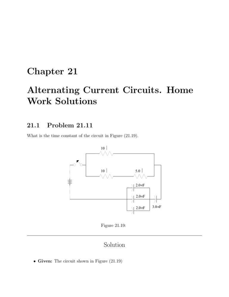
Chapter 21 Alternating Current Circuits. Home Work Solutions 21.1 Problem 21.11 What is the time constant of the circuit in Figure (21.19). 10 Ω 10 Ω 5.0 Ω 2.0µF 2.0µF 2.0µF Figure 21.19: Solution • Given: The circuit shown in Figure (21.19) 3.0µF 2 CHAPTER 21. ALTERNATING CURRENT CIRCUITS. HOME WORK SOLUTIONS • Required: The time constant τ of the circuit. The time constant of an RC circuit is: τ = RC where R and C are the equivalent resistance and capacitance of the circuit. We then need to find the Equivalent R and the equivalent C of the circuit. The 10 Ω and the 5.0 Ω are connected in series, so their equivalent resistance is 15 Ω. This 15 Ω is connected to the 10 Ω resistor in parallel, so their equivalent resistance R = (15 × 10)/(15 + 10) = 6.0 Ω. The three 2.0 µF capacitors are connected in parallel, so their equivalent capacitance is 6.0 µF . This 6.0 µF capacitance is connected to the 3.0 µF capcacitance in parallel, so their equivalent capacitance C = (6.0 × 3.0)/(6.0 + 3.0) = 2.0 µF . The time constant of the circuit is then: τ = = = = RC 6.0 × 2.0 × 10−6 12 × 10−6 s 12 µs 21.2. PROBLEM 21.23 21.2 3 Problem 21.23 A transformer is designed to have an output of 12.6 V rms when connected to an input of 110 V rms. If the input is raised to 120 V , what is the peak value of the output voltage? Solution rms rms • Given: A transformer with Vout1 = 12.6 V , amd Vin1 = 110 V peak rms • Required: The Vout2 when Vin2 = 120 V In a transformer without energy loss the ratio of Vin /Vout is always the same. We then have: rms rms Vin2 Vin1 = rms rms Vout1 Vout2 rms Vout2 rms V rms Vout2 = rms in2 Vin2 12.6 = × 120 110 √ rms V peak = 2V √ 12.6 rms × 120 Vout2 = 2× 110 = 19.4 V 4 CHAPTER 21. ALTERNATING CURRENT CIRCUITS. HOME WORK SOLUTIONS 21.3 Problem 21.39 A series RC circuit is driven by an alternating voltage source at a frequency of 100 Hz. (a) If R = 330 Ω and C = 100 µF , what is the phase angle between current and voltage? (b) What is the phase angle between capacitor voltage and resistor voltage? (c) What is the phase angle between capacitor current and resistor current? Solution • Given: A series RC circuit with R = 330 Ω and C = 100 µF and driven by an AC voltage with f = 100Hz. • Required: The phase angle φ between the circuit’s voltage and current, the phase angle between VC and VR , and the phase angle between IC and IR . (a) In and RLC circuit, the phase angle between the the voltage and the current is given by: XL − XC φ = arctan R where XL is the reactance of the inductance and XC is the reactance of the capacitor. The circuit under consideration in this problem has no inductance, we then put XL = 0 and φ becomes: −XC φ = arctan R the capacitive reacatance is given by: XC = 1 2πf C we then have: φ = = = = = −XC arctan R −1 arctan 2πRC −1 arctan 2π × 330 × 100 × 10−6 arctan(−4.82 × 10⁻² ) −2.8◦ 21.3. PROBLEM 21.39 5 (b) The phase angle between VC and I is −90◦ . However, the phase angle between the VR an I is 0◦ . Therefore, the phase angle between VC and VR is −90◦ . (c) The current in the circuit is the same throughout, that is, the same current flows through the capacitor and the resistor. Therefore, the phase angle between the capacitor current and resistor current is 0◦ . 6 CHAPTER 21. ALTERNATING CURRENT CIRCUITS. HOME WORK SOLUTIONS 21.4 Problem 21.50 A 15 µF capacitor is connected across a 0.50 H inductor. The capacitor is initially charged to 30 V (a) What is the peak current in the circuit? (b) What is the frequency of the oscillations? Solution • Given: An RL circuit with a capacitor C = 15 µF and inductor L = 0.5 H. The capacitor is initially charged to 30 V . • Required: The peak current and oscillation frequency in the the circuit. The capacitor will discharge through the inductor. This means that the electric field in the capacitor will decrease while a magnetic field will build up inside the inductor. Once the capacitor is fully discharged, there will be no current in the circuit and the magnetic field will start to decrease. This in turn will establish an emf and a current that will charge the capacitor in the opposite direction. Once the magnetic field drops to zero, the capacitor will no longer charge, it will then start to discharge and the process will be repeated all over again. As a result, the energy in the circuit will be stored as an electric field then change to a magnetic field and then back to an electric field. In addition, an electric current will start at maximum, decrease to zero, increase to a maximum in the opposite direction, decrease to zeros and so on and so forth. (a) The initial amount of energy in the circuit is the energy stored in the capacitor. This energy is changed into magnetic energy in the inductor, we then have: 1 1 2 CV 2 = LI 2 2 peak r CV 2 Ipeak = r L 15 × 10−6 × (30)2 = 0.5 = 0.16 A 21.4. PROBLEM 21.50 7 (b) The frequency of the process will be determined by the natural frequency f of the circuit which is given by: f = 1 √ 2π LC 1 2π 0.5 × 15 × 10−6 = 58.1 Hz = √


