Final class notes
advertisement
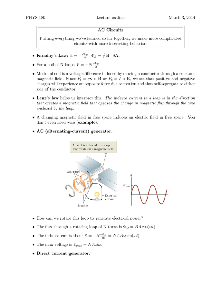
PHYS 189 Lecture outline March 3, 2014 AC Circuits Putting everything we’ve learned so far together, we make more complicated circuits with more interesting behavior. • Faraday’s Law: E = − dΦdtB , ΦB = H B · dA. • For a coil of N loops, E = −N dΦdtB • Motional emf is a voltage difference induced by moving a conductor through a constant magnetic field. Since Fb = qv × B or Fb = I × B, we see that positive and negative charges will experience an opposite force due to motion and thus self-segregate to either side of the conductor. • Lenz’s law helps us interpret this: The induced current in a loop is in the direction that creates a magnetic field that opposes the change in magnetic flux through the area enclosed by the loop. • A changing magnetic field in free space induces an electric field in free space! You don’t even need wire (example). • AC (alternating-current) generator.: • How can we rotate this loop to generate electrical power? • The flux through a rotating loop of N turns is ΦB = BA cos(ωt) • The induced emf is then: E = −N dΦdtB = N ABω sin(ωt). • The max voltage is Emax = N ABω. • Direct current generator: PHYS 189 Lecture problems outline 2 of 10 March 3, 2014 • Induced EMF • Each circuit may have a different self-inductance proportional to the current passing through it, which we right as: E = −L dI . dt • SI unit of inductance is called henery H, 1 H = 1 V·s/A. PHYS 189 Lecture problems outline 3 of 10 • For solenoids, EL = −N dΦdtB = −L dI , so L = N ΦB /I. dt • Self-inductance of circuit can be represented as an inductor: • RL Circuits: which behaves with the equation E − IR − L with solution I= dI =0 dt E E 1 − e−Rt/L = 1 − e−t/τ R R The value, τ= L R is called the RL circuit time constant. • This is why real currents don’t go from 0 to I instantly. • We switch to b, and find that the current behaves as: I= E −Rt/L E e = e−t/τ R R March 3, 2014 PHYS 189 Lecture problems outline 4 of 10 March 3, 2014 • Energy in magnetic field can be found by: IE = I 2 R + LI so that dI dt dU dI 1 = LI → U = LI 2 dt dt 2 • Mutual inductance: Flux created by one coil induces current in a nearby coil. The two circuits will have a value called Mutual Inductance: M12 = N2 Φ12 I1 where circuit 1, with current I1 , sets up a magnetic flux Φ12 in the second coil with N2 turns. • The voltage in the second coil is, dΦ12 d E2 = −N2 = −N2 dt dt M12 I1 N2 = −M12 • The current changing in the second coil, in turn, induces, E1 = −M21 • LC Circuit: dI2 dt dI1 dt PHYS 189 Lecture problems outline 5 of 10 March 3, 2014 Assuming ideal circumstances (no resistors, ignore radiation), the energy in the circuit is: Q2 1 2 U = Uc + UL = + LI 2C 2 and dU Q dQ dI d2 Q 1 = + LI → Q =− 2 dt C dt dt dt LC whose solution is, Q = Qmax cos(ωt + φ) √ where ω = 1/ LC and φ is a phase constant that depends on the initial state of the circuit at time t = 0. If I = 0 at t = 0, then φ = 0. In such a case, Q = Qmax cos(ωt) and I = −ωQmax sin(ωt) In other words, the circuit cycles back and forth forever! PHYS 189 Lecture problems outline 6 of 10 • What happens if we throw a resistor in the circuit? March 3, 2014 PHYS 189 Lecture problems outline 7 of 10 March 3, 2014 The change in energy due to a resistor is, dU = −I 2 R dt which sets up the equation: LI dI Q dQ + = −I 2 R dt C dt which we can recast as, d2 Q dQ Q + =0 +R 2 dt dt C This equation is called the damped harmonic equation, whose solution is, L Q = Qmax e−Rt/2L cos(ωd t) with s ωd = 1 − LC R 2L 2 The circuit oscillates, but it also decays in time: • As we saw previously, AC voltage supplies oscillate as: ∆v = ∆Vmax sin ωt. • A resistor supplied with AC voltage: PHYS 189 Lecture problems outline 8 of 10 • Applying Kirchoff’s loop rule: ∆v − iR R = 0 iR = ∆v ∆Vmax = sin ωt ≡ Imax sin ωt R R Then the voltage drop across the resistor varies: ∆vR = iR R = Imax R sin ωt • Inductors can be supplies with AC voltage: with the loop rule: ∆v − L diL =0 dt We rearrange to get, diL = ∆Vmax ∆Vmax sin ωtdt → iL = − cos ωt L ωL The inductor and applied AC current are out of phase by π/2 rad. • Write Imax = ∆Vmax ωL • Call XL ≡ ωL the inductive reactance then we have: Imax = ∆Vmax XL which puts it in a form comparable to I = V /R. • Finally, we find that the voltage across the inductor is, ∆vL = −L diL = −∆Vmax sin ωt = −Imax XL sin ωt dt March 3, 2014 PHYS 189 Lecture problems outline 9 of 10 March 3, 2014 • Capacitors in an AC circuit: • Using the same method of derivation as for the previous cases, we can find that the current in this circuit is, iC = ωC∆Vmax cos ωt we then have Imax = ωC∆Vmax = where XC = 1 ωC ∆Vmax ∆Vmax ≡ 1/ωC XC is called the capacitive reactance. • Finally, the RLC circuit: • Refer to your book for the derivation, but for this circuit, we define the impedence q Z ≡ R2 + (XL − XC )2 and ∆Vmax Z with a phase angle between the current and voltage of: XL − XC −1 φ = tan R Imax = PHYS 189 Lecture problems outline 10 of 10 March 3, 2014 • When XL > XC (which occurs at high frequencies), the phase angle is positive, signifying that the current lags the applied voltage as in Active Figure 33.15b. We describe this situation by saying that the circuit is more inductive than capacitive. When XL < XC , the phase angle is negative, signifying that the current leads the applied voltage, and the circuit is more capacitive than inductive. When XL = XC , the phase angle is zero and the circuit is purely resistive. • Because power is lost through resistance at a rate of I 2 R, it is more efficient to transmit power at a very high voltage (thus lower current and less power loss). • 350 kV lines are common, which are often brought down to 20,000 V at distributing stations, then 4,000 V before residential distribution, and then 120V and 240 V to customers. How is this accomplished? • AC transformer: • dΦB dt dΦB ∆v2 = −N2 dt N2 ∆V2 = ∆v1 N1 ∆v1 = −N1
