REC2R - Carlo Gavazzi AB
advertisement

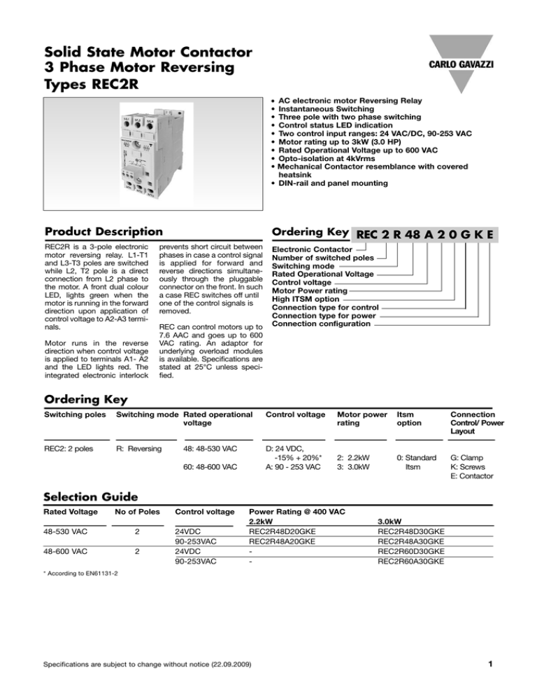
Solid State Motor Contactor 3 Phase Motor Reversing Types REC2R AC electronic motor Reversing Relay Instantaneous Switching Three pole with two phase switching Control status LED indication Two control input ranges: 24 VAC/DC, 90-253 VAC Motor rating up to 3kW (3.0 HP) Rated Operational Voltage up to 600 VAC Opto-isolation at 4kVrms Mechanical Contactor resemblance with covered heatsink • DIN-rail and panel mounting • • • • • • • • • Product Description REC2R is a 3-pole electronic motor reversing relay. L1-T1 and L3-T3 poles are switched while L2, T2 pole is a direct connection from L2 phase to the motor. A front dual colour LED, lights green when the motor is running in the forward direction upon application of control voltage to A2-A3 terminals. Motor runs in the reverse direction when control voltage is applied to terminals A1- A2 and the LED lights red. The integrated electronic interlock Ordering Key REC 2 R 48 A 2 0 G K E prevents short circuit between phases in case a control signal is applied for forward and reverse directions simultaneously through the pluggable connector on the front. In such a case REC switches off until one of the control signals is removed. REC can control motors up to 7.6 AAC and goes up to 600 VAC rating. An adaptor for underlying overload modules is available. Specifications are stated at 25°C unless specified. Electronic Contactor Number of switched poles Switching mode Rated Operational Voltage Control voltage Motor Power rating High ITSM option Connection type for control Connection type for power Connection configuration Ordering Key Switching poles Switching mode Rated operational voltage Control voltage REC2: 2 poles R: Reversing D: 24 VDC, -15% + 20%* A: 90 - 253 VAC 48: 48-530 VAC 60: 48-600 VAC Motor power rating Itsm option Connection Control/ Power Layout 2: 2.2kW 3: 3.0kW 0: Standard Itsm G: Clamp K: Screws E: Contactor Selection Guide Rated Voltage No of Poles 48-530 VAC 2 48-600 VAC 2 Control voltage 24VDC 90-253VAC 24VDC 90-253VAC Power Rating @ 400 VAC 2.2kW REC2R48D20GKE REC2R48A20GKE - 3.0kW REC2R48D30GKE REC2R48A30GKE REC2R60D30GKE REC2R60A30GKE * According to EN61131-2 Specifications are subject to change without notice (22.09.2009) 1 REC2R General Specifications Rated Operational voltage Operational voltage Range Blocking voltage Operational frequency range Power factor REC..48.. 480 VAC 48-530 VAC 1200 Vp 45 - 65 Hz >0.5 @ rated voltage REC..60.. 600 VAC 48-600 VAC 1600 Vp 45 - 65 Hz >0.5 @ rated voltage REC...D.. 24 VDC 15-32 VDC (according to EN61131-2) 10 mA 15 VDC 32 VDC 1 VDC 5 ms 15 ms N/A 80 ms Forward: Green Reverse: Red REC...A.. 230 VAC 90 - 253 VAC Control specifications Rated control input voltage Control voltage range Maximum Input current Pick-up voltage Maximum Reverse voltage Drop-out voltage Response time pick-up Response time drop-out Operational frequency range Maximum Time delay F- -> R, F <-- R LEDs 15 mA 90 VAC N/A 10 VAC 30 ms 30 ms 45 - 65 Hz 100 ms Forward: Green Reverse: Red Connection Specifications POWER CONNECTIONS (75°C,Copper Cables) CONTROL CONNECTIONS (75°C,Copper Cables) Connection Type Illustration of terminal Screw terminal Connection Type Spring loaded* Illustration of terminal Captive Clamp Rigid (Solid) 2 x 1.5..2.5mm² (2 x AWG16..14) 2 x 2.5..6mm² (2 x AWG14..10) Type Stranded Pluggable - 2 x 1..2.5mm² (2 x AWG17..14) 2 x 2.5..6mm² (2 x AWG14..10) 1 x 10mm² (1 x AWG8) Solid 1 x 0.05..2.5mm² ( 1 x AWG 24..14) 10mm N/A N/A 1.5N 3N Pluggable 1 x 0.05..1.5mm² ( 1 x AWG30..16) 1 x 0.05..2.5mm² (1 x AWG30..14) 6 - 7.5mm 0.5Nm (Philips bit) M3 1.5N 3N 15mΩ 15mΩ Finely stranded with end sleeve Flexible w/o end sleeves Stripping length Tightening torque Screw size Aperture for termination lug (fork type) 2 x 1.5..2.5mm² (2 x AWG16..14) 2 x 2.5..6mm² (2 x AWG14..10) 10mm 2Nm (Pozidriv 2 bit) M4 Stripping length Tightening torque Screw Size Withdrawal Force Insertion Force Max Contact Resistance Max 11mm * Available on request 2 Specifications are subject to change without notice (22.09.2009) REC2R Load Specifications Rated Operational Current AC-53a @ 400Vrms, to IEC, for trip Classes 10, 20, 30 Horizontal space between units REC......20 REC..48..30 REC..60..30 No. of poles Maximum On-state voltage drop @ rated current Off-state leakage current @rated voltage and frequency Critical dV/dt* Motor Rating @ 40° @ 50° 6.2A 7.6A 7.6A 45 mm 5.8A 6.8A 6.8A @ 60° 5.3A 6.2A 6.2A @ 40° @ 50° @ 60° 0 mm 5.8A 5.3A 5.8A 5.8A 2 1.6 Vrms Imin Itsm All Cases 400mA 600Ap 400mA 600Ap 400mA 600Ap 4.3A 4.9A - < 3 mArms 1000V/us (45mm space between adjacent units) HP @ 40 / 50 / 60°C, according to UL508 230V kW @ 40 / 50 / 60°C, according to IEC60947-4-2 400V 480V 600V 230V 400V 480V 600V - REC2…20 1½ / 1 / 1 3/2/2 3/3/3 - 1.5 / 1.1 / 1.1 2.2 / 2.2 / 2.2 3.0 / 3.0 / 2.2 REC2..48..30 2/2/1 3/3/3 5/3/3 - 1.5 / 1.5 / 1.5 3.0 / 2. 2 / 2.2 4.0 / 3.0 / 3.0 - REC2..60..30 2 / 2 / 1½ 3/3/3 5/3/3 5/5/5 1.5 / 1.5 / 1.5 3.0 / 2. 2 / 2.2 4.0 / 3.0 / 3.0 5.5 / 4.0 / 4.0 Environmental Specifications Housing Specifications Operating Temperature Storage Temperature RoHS compliant Impact resistance Vibration resistance Relative humidity Pollution degree Installation category Degree of finger protection Installation altitude Weight Housing Material Flame class Housing Colour Dimensions (h x w x d) (without input plug) -25°C to 60°C -40°C to 100°C Yes 15/11 g/ms 2g < 95% non-condensing @ 40 °C 2 III IP20 0- 1000m. Above 1000m derate linearly by 1% of FLC per 100m up to a maximum of 2000m approx 300g Nylon PA66 UL94-V0 RAL7035 105 x 45 x 90 mm Isolation Dielectric withstand voltage input to output ≥ 4000V AC rms * Specification @ Tj (init.) = 25˚C and t = 10ms Specifications are subject to change without notice (22.09.2009) 3 REC2R Short Circuit Protection (according to EN/IEC 60947-4-2 and UL508) Short Circuit Current Rating Type of coordination: 1 UL rated short circuit current RK5 fuse Type of coordination: 2 Rated short circuit Semiconductor fuse REC2B48.20 REC3B…..20 REC2B...30 REC3B48...30 REC2B48..40 5kA 5kA 5kA 12A 15A 15A Y220913 6.9 CP GRC 22.58 50 Y220913 6.9 CP GRC 22.58 50 Y220913 6.9 CP GRC 22.58 50 Agency Approvals & EMC CE marking Low Voltage Directive EMC Immunity EMC Emission Electrostatic Discharge (ESD) Immunity Electrical Fast Transient Burst Immunity Output: 4kV / 5kHz Output: 2kV / 5kHz Input: 2kV / 5kHz Voltage Interruptions Immunity 0% for 5000ms Radio Interference voltage emissions (conducted)* 150K - 30MHz IEC / EN 60947-4-2 IEC / EN 61000-6-3 IEC / EN 61000-6-1 IEC / EN 61000-4-2 8kV, PC2 Air discharge 4kV, PC1 Contact IEC / EN 61000-4-4 Performance criteria 2 Performance criteria 1 Performance criteria 1 IEC / EN 61000-4-11 Performance criteria 2 IEC / EN 55011, IEC/EN 60947-4-2 Class A (industrial)* UL Approval Restrictions of hazardous substances Radiated Radio Frequency Immunity 10 V/m, 80 - 2700 MHz Electrical Surge Immunity Output, line to line Output, line to earth Input, line to line Intput, line to earth Conducted Radio Frequency Immunity 10V/m, 0.15 - 80 MHz Voltage Dips Immunity 0% for 10ms/20ms, 70% for 500ms 40% for 200ms Radio Interference field emissions (radiated) 30 - 1000 MHz * 4 cULus listed (E172877) RoHS EN 61000-4-3 Performance criteria 1 IEC / EN 61000-4-5 1kV, performance criteria 2kV, performance criteria 1kV, performance criteria 2kV, performance criteria 1 1 2 2 IEC / EN 61000-4-6 Performance criteria 1 IEC / EN 61000-4-11 Performance criteria 2 Performance criteria 1 IEC / EN 55011, IEC/EN 60947-4-2 Class B (light industry) This product is designed and constructed as an EMC Class A device. The use of this product in residential applications could lead to radio interferences. In such applications, additional external filtering may be required. Specifications are subject to change without notice (22.09.2009) REC2R Connection Diagrams REC2R - Leg connection for star (wye) and delta L1 L2 L3 L1 L2 L3 Dimensions 105 ± 0.5mm 55.1 ± 0.5mm 86 ± 0.5 mm 82.2 ± 0.5 mm 45mm max. 99.4 ± 0.5 mm All dimensions in mm Specifications are subject to change without notice (22.09.2009) 5 REC2R Characteristic Curves and Operating Cycles Maximum allowable number of starts depending on the Tn and Ton In In: Inrush current for direct on line starting Ie: Rated full load current IL: Load Current Tn: Time during inrush current In Te: Time during full load current Ie or IL Tx: Off time TON = Tn + Te Ie IL Tn Te Tx TON Curves: No. of switching cycles per hour versus tON `Ü~êí=kçK=N= ílk EëF= MKN= N NM= NMM= NMMM= In I Z TKOI= L Z N Ie Ie kìãÄÉê=çÑ=pïáíÅÜÉë=éÉê=eçìê= qå Z MKMRë= qå Z MKNë= qå Z MKOë= qå Z MKQë= qå Z MKUë= qå Z NKSë= qå Z PKOë= NUMM= NRMM= OUM= PU= J VNM= UMM= PMM= PU= J J= QOM= OR= PU= J J= OOM= NSM= PR= J J= NMO= VM= PR= J J= J= QM= OR= J J= J= NR= S= J `Ü~êí=kçK=O= In I Z TKOI= L Z MKS= Ie Ie = ílk EëF= MKN= N NM= NMM= NMMM= kìãÄÉê=çÑ=pïáíÅÜÉë=éÉê=eçìê= qå Z MKMRë= qå Z MKNë= qå Z MKOë= qå Z MKQë= qå Z MKUë= qå Z NKSë= qå Z PKOë= NVMM= NUMM= PVM= PU= J VMM= URM= PVM= PU= J J= QQM= PRM= PU= J J= NOM= NVM= PU= J J= NNM= NMM= OR= J J= J= RM= OR= J J= J= OR= OM= J `Ü~êí=kçK=P= ílk= EëF= MKN= N NM= NMM= NMMM= In I Z QI= L Z N Ie Ie kìãÄÉê=çÑ=pïáíÅÜÉë=éÉê=eçìê= qå Z MKMRë= qå Z MKNë= qå Z MKOë= qå Z MKQë= qå Z MKUë= qå Z NKSë= qå Z PKOë= RNMM= OTMM= ORM= PS= J OUMM= NVMM= ORM= PS= J J= NNMM= ORM= PS= J J= SRM= OVM= PS= J J= PRM= OMM= PS= J J= J= NQM= PS= J J= J= TR= PM= J `Ü~êí=kçK=Q= ílk= EëF= MKN= N NM= NMM= NMMM= 6 In I Z QI= L Z MKS= Ie Ie kìãÄÉê=çÑ=pïáíÅÜÉë=éÉê=eçìê= qå Z MKMRë= qå Z MKNë= qå Z MKOë= qå Z MKQë= qå Z MKUë= qå Z NKSë= qå Z PKOë= RRMM= PQMM= PRM= PS= J OVMM= OPMM= PRM= PS= J J= NQMM= PRM= PS= J J= TMM= PRM= PS= J J= PRM= OUM= PS= J J= J= NTM= PS= J J= J= UM= PS= J Specifications are subject to change without notice (22.09.2009) REC2R Accessories Motor overload Relay adapter. Part Number: REC3ADAPTOR Compatible with: Manufacturer Carlo Gavazzi ABB Siemens Series CGT22 TA 3RU11 Example CGT-22.8 TA25DU-8.5 3RU1126-1FB0 Specifications are subject to change without notice (22.09.2009) 7


